📝 3 Aug 2021
Today we shall magically transform any RISC-V BL602 Board into a Light Sensor!
We'll do this two ways...
-
First we code the firmware in C
(By calling the BL602 IoT SDK)
-
Then we port the C firmware to Rust with...
Rust Wrapper for BL602 IoT SDK
(New to Rust? No worries we have tips for you!)
Wait... Do all BL602 Boards have an onboard Light Sensor?
Nope, all we need is a BL602 Board with an LED!
Reading the LED with BL602's Analog-to-Digital Converter (ADC) will turn it into a simple, improvised Light Sensor.
Amazing! Will this work with any BL602 Board?
We have tested this with PineCone BL602 and its onboard LED.
It will probably work with any BL602 / BL604 Board with an onboard or external LED: Ai-Thinker Ai-WB2, PineDio Stack, Pinenut, DT-BL10, MagicHome BL602, ...
Will our Light Sensor detect any kind of light?
Our LED-turned-Light-Sensor works best for detecting sunlight... We'll learn why in a while.
(Yep It's Always Sunny in Singapore ... So this Sunlight Sensor won't be so useful in Singapore 😂)
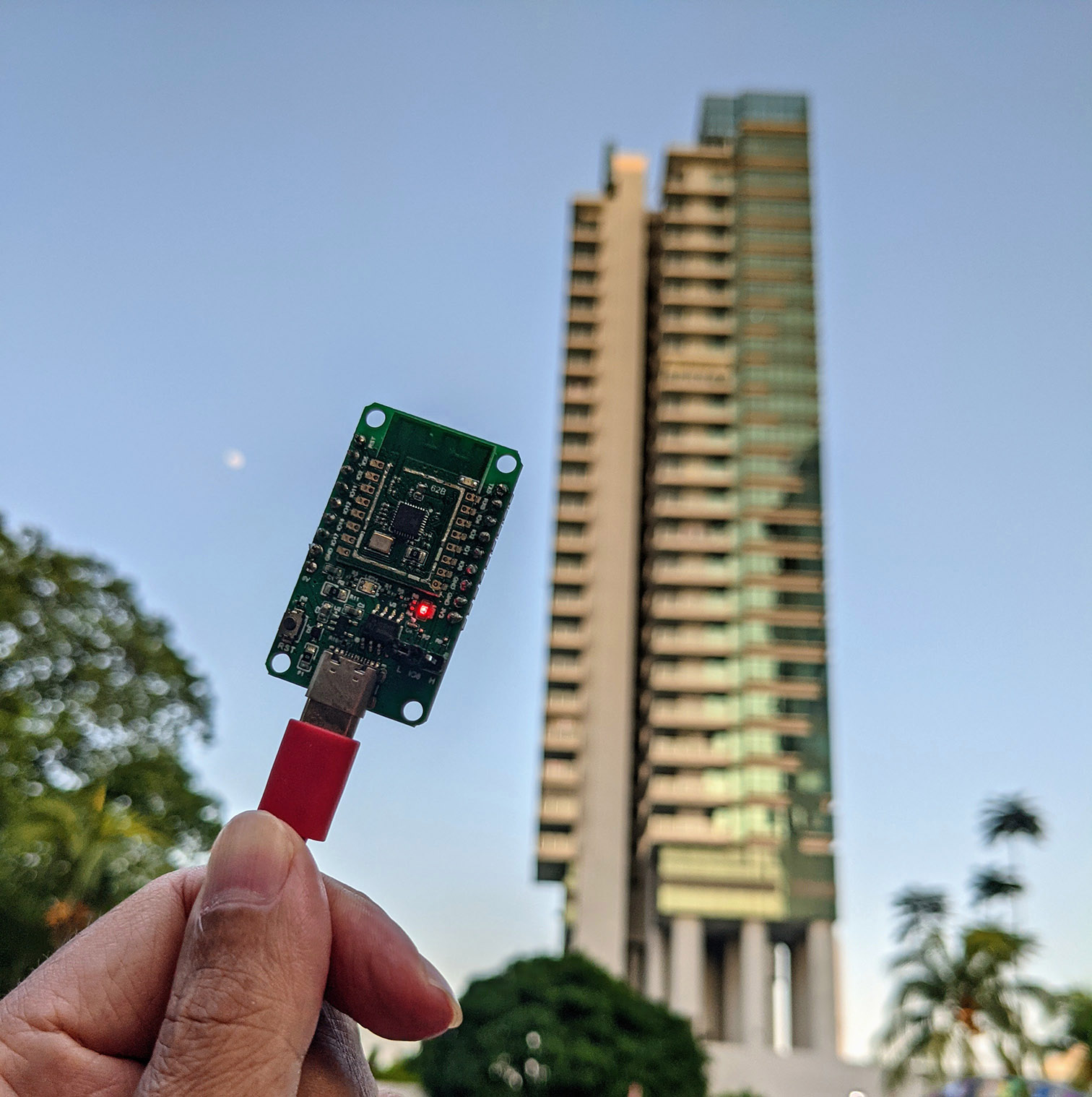
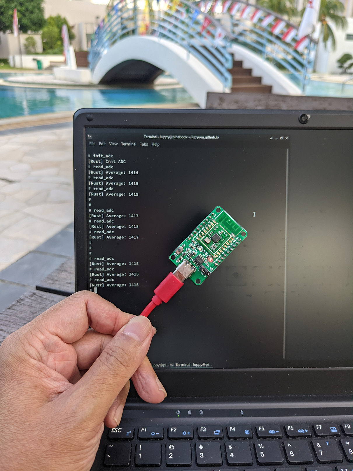
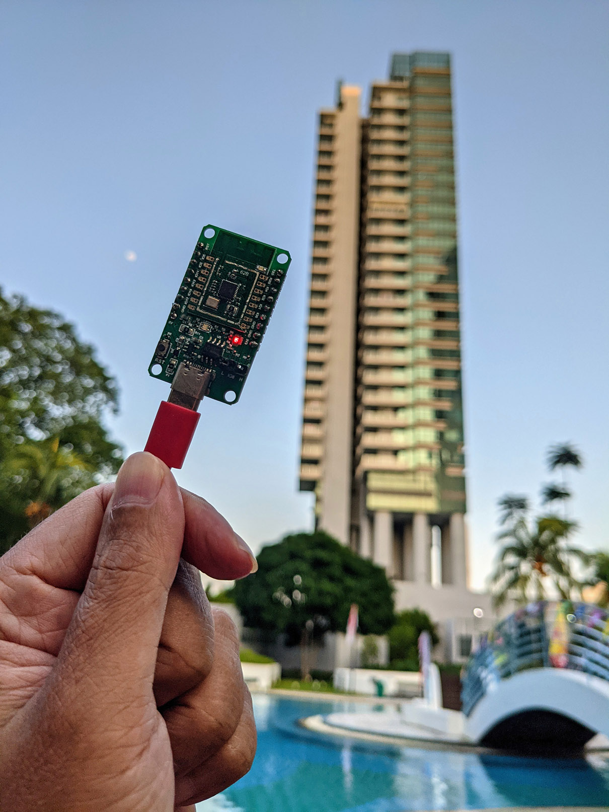
Testing the improvised Light Sensor on PineCone BL602 RISC-V Board. BTW that's the moon
On PineCone BL602, there's a Blue LED connected on GPIO Pin Number 11...
(From PineCone BL602 Schematic)
For light sensing, we shall read the voltage from this LED GPIO with BL602's Analog-to-Digital Converter (ADC).
(Because LEDs will produce a current when exposed to light. See this)
Let's study the C Firmware for BL602 ADC: sdk_app_adc2
By calling the BL602 ADC Low Level HAL (Hardware Abstraction Layer), we shall...
-
Initialise the ADC Channel for reading our LED GPIO
-
Compute the average value of the ADC Samples that have been read
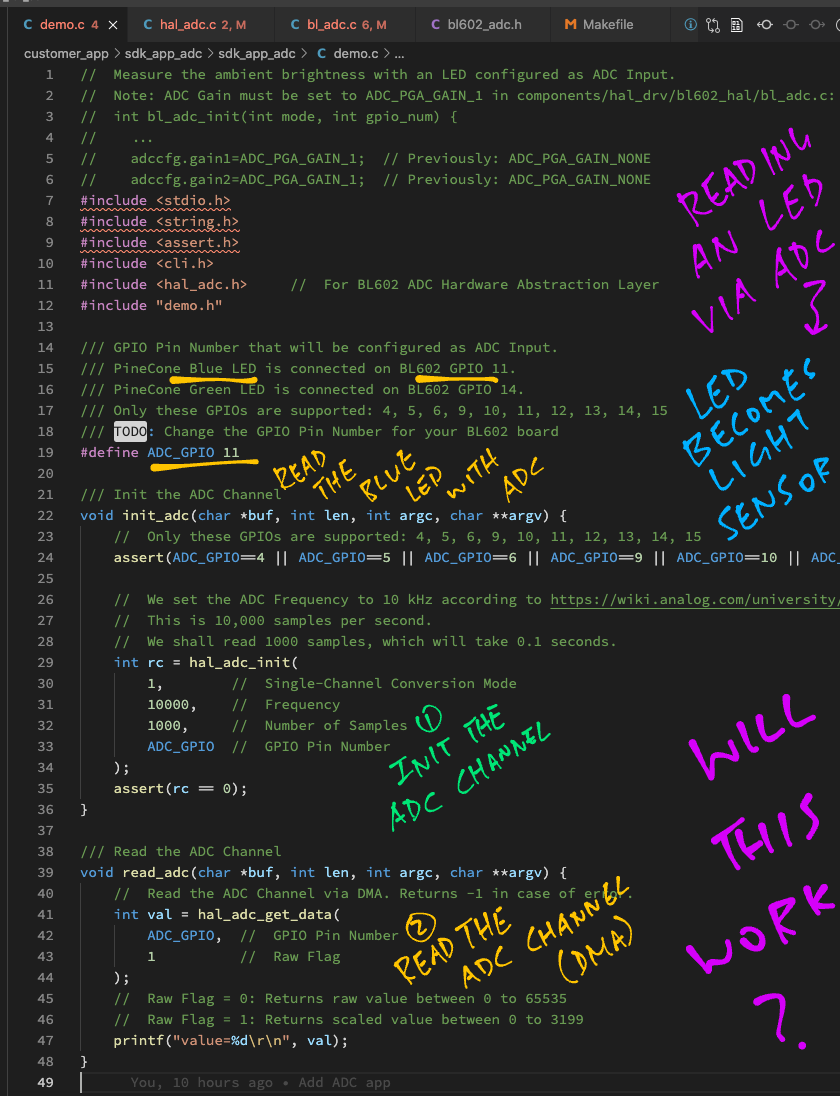
We start by defining the GPIO Pin Number that will be read via ADC: demo.c
/// GPIO Pin Number that will be configured as ADC Input.
/// PineCone Blue LED is connected on BL602 GPIO 11.
/// PineCone Green LED is connected on BL602 GPIO 14.
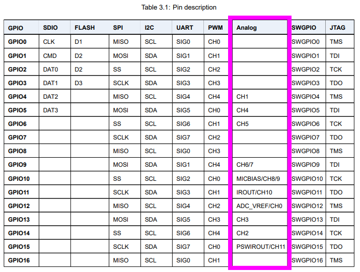
/// Only these GPIOs are supported: 4, 5, 6, 9, 10, 11, 12, 13, 14, 15
/// TODO: Change the GPIO Pin Number for your BL602 board
#define ADC_GPIO 11
Not all GPIOs are supported by BL602's ADC!
According to the BL602 Reference Manual, only the following GPIOs are supported for ADC: 4, 5, 6, 9, 10, 11, 12, 13, 14, 15
Next we define the ADC Frequency. We shall read 10,000 ADC Samples every second...
/// We set the ADC Frequency to 10 kHz according to <https://wiki.analog.com/university/courses/electronics/electronics-lab-led-sensor?rev=1551786227>
/// This is 10,000 samples per second.
#define ADC_FREQUENCY 10000  //  Hz
For computing the average, we shall remember the last 1,000 ADC Samples read...
/// We shall read 1,000 ADC samples, which will take 0.1 seconds
#define ADC_SAMPLES 1000
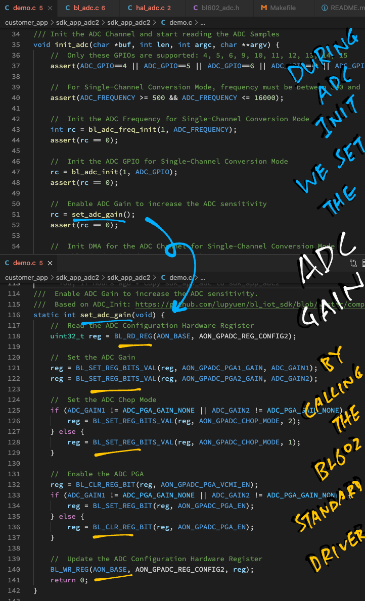
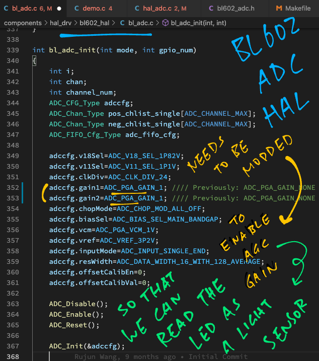
Finally we set the ADC Gain to increase the sensitivity of the ADC...
/// Set ADC Gain to Level 1 to increase the ADC sensitivity.
/// To disable ADC Gain, set `ADC_GAIN1` and `ADC_GAIN2` to `ADC_PGA_GAIN_NONE`.
/// See <https://github.com/lupyuen/bl_iot_sdk/blob/master/components/bl602/bl602_std/bl602_std/StdDriver/Inc/bl602_adc.h#L133-L144>
#define ADC_GAIN1 ADC_PGA_GAIN_1
#define ADC_GAIN2 ADC_PGA_GAIN_1
More about ADC Gain in a while.
Here's how we initialise the ADC Channel for reading our LED GPIO: demo.c
/// Command to init the ADC Channel and start reading the ADC Samples.
/// Based on `hal_adc_init` in <https://github.com/lupyuen/bl_iot_sdk/blob/master/components/hal_drv/bl602_hal/hal_adc.c#L50-L102>
void init_adc(char *buf, int len, int argc, char **argv) {
  //  Only these GPIOs are supported: 4, 5, 6, 9, 10, 11, 12, 13, 14, 15
  assert(ADC_GPIO==4 || ADC_GPIO==5 || ADC_GPIO==6 || ADC_GPIO==9 || ADC_GPIO==10 || ADC_GPIO==11 || ADC_GPIO==12 || ADC_GPIO==13 || ADC_GPIO==14 || ADC_GPIO==15);

  //  For Single-Channel Conversion Mode, frequency must be between 500 and 16,000 Hz
  assert(ADC_FREQUENCY >= 500 && ADC_FREQUENCY <= 16000);

  //  Init the ADC Frequency for Single-Channel Conversion Mode
  int rc = bl_adc_freq_init(1, ADC_FREQUENCY);
  assert(rc == 0);
Our init_adc Command begins by validating the GPIO Pin Number and ADC Frequency.
Then it calls bl_adc_freq_init to set the ADC Frequency.
(Functions named bl_adc_* are defined in the BL602 ADC Low Level HAL)
The first parameter to bl_adc_freq_init selects the ADC Mode...
-
ADC Mode 0: Scan Conversion Mode
BL602 ADC Controller reads One ADC Sample from Multiple ADC Channels.
(So it's scanning across multiple ADC Channels, recording one sample per channel)
-
ADC Mode 1: Single-Channel Conversion Mode
BL602 ADC Controller reads Multiple ADC Samples continuously from One ADC Channel.
(This is the mode we're using)
Next we set the ADC GPIO Pin Number for ADC Mode 1 (Single-Channel Conversion)...
  //  Init the ADC GPIO for Single-Channel Conversion Mode
  rc = bl_adc_init(1, ADC_GPIO);
  assert(rc == 0);
To increase the ADC sensitivity, we set the ADC Gain...
  //  Enable ADC Gain to increase the ADC sensitivity
  rc = set_adc_gain(ADC_GAIN1, ADC_GAIN2);
  assert(rc == 0);
(More about this in a while)
BL602 ADC Controller shall transfer the ADC Samples directly into RAM, thanks to the Direct Memory Access (DMA) Controller...
  //  Init DMA for the ADC Channel for Single-Channel Conversion Mode
  rc = bl_adc_dma_init(1, ADC_SAMPLES);
  assert(rc == 0);
(First parameter of bl_adc_dma_init is the ADC Mode)
We configure the GPIO Pin for ADC Input...
  //  Configure the GPIO Pin as ADC Input, no pullup, no pulldown
  rc = bl_adc_gpio_init(ADC_GPIO);
  assert(rc == 0);
We set the DMA Context for the ADC Channel...
  //  Get the ADC Channel Number for the GPIO Pin
  int channel = bl_adc_get_channel_by_gpio(ADC_GPIO);

  //  Get the DMA Context for the ADC Channel
  adc_ctx_t *ctx = bl_dma_find_ctx_by_channel(ADC_DMA_CHANNEL);
  assert(ctx != NULL);

  //  Indicate that the GPIO has been configured for ADC
ctx->chan_init_table |= (1 << channel);(bl_dma_find_ctx_by_channel is defined in BL602 DMA HAL)
Finally we start the ADC Channel...
  //  Start reading the ADC via DMA
  bl_adc_start();
}
BL602 ADC Controller will read the ADC Samples continuously (from the GPIO Pin) into RAM (until we stop the ADC Channel).
After starting the ADC Channel, how do we fetch the ADC Samples that have been read?
Let's find out in demo.c ...
/// Command to compute the average value of the ADC Samples that have just been read.
/// Based on `hal_adc_get_data` in <https://github.com/lupyuen/bl_iot_sdk/blob/master/components/hal_drv/bl602_hal/hal_adc.c#L142-L179>
void read_adc(char *buf, int len, int argc, char **argv) {
  //  Get the ADC Channel Number for the GPIO Pin
  int channel = bl_adc_get_channel_by_gpio(ADC_GPIO);

  //  Get the DMA Context for the ADC Channel
  adc_ctx_t *ctx = bl_dma_find_ctx_by_channel(ADC_DMA_CHANNEL);
  assert(ctx != NULL);

  //  Verify that the GPIO has been configured for ADC
  assert(((1 << channel) & ctx->chan_init_table) != 0);
Our read_adc Command begins by verifying the DMA Context for the ADC Channel.
Next we check whether the ADC Sampling has been completed for the ADC Channel...
  //  If ADC Sampling is not finished, try again later
  if (ctx->channel_data == NULL) {
    printf("ADC Sampling not finished\r\n");
    return;
  }
Remember that the BL602 ADC Controller will read ADC Samples continuously and write the last 1,000 samples to RAM (via DMA).
Let's copy the last 1,000 ADC Samples from the DMA Context (in RAM) to a Static Array adc_data...
  //  Static array that will store 1,000 ADC Samples
  static uint32_t adc_data[ADC_SAMPLES];

  //  Copy the read ADC Samples to the static array
  memcpy(
    (uint8_t*) adc_data,             //  Destination
    (uint8_t*) (ctx->channel_data),  //  Source
    sizeof(adc_data)                 //  Size
  );
Then we compute the average value of the ADC Samples in adc_data...
  //  Compute the average value of the ADC Samples
  uint32_t sum = 0;
  for (int i = 0; i < ADC_SAMPLES; i++) {
    //  Scale up the ADC Sample to the range 0 to 3199
    uint32_t scaled = ((adc_data[i] & 0xffff) * 3200) >> 16;
    sum += scaled;
  }
  printf("Average: %lu\r\n", (sum / ADC_SAMPLES));
}
The default ADC Configuration has roughly 12 Bits of Resolution per ADC Sample.
Thus we scale each ADC Sample to the range 0 to 3199.
And that's how we code BL602 ADC Firmware in C!
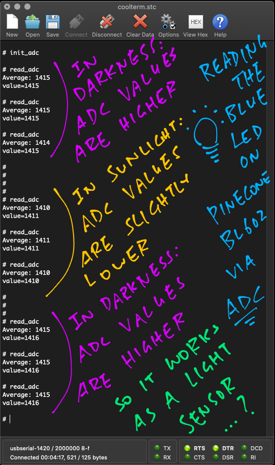
Watch what happens when we flash and run the C Firmware for BL602 ADC: sdk_app_adc2
-
Enter this command to initialise the ADC Channel...
init_adc(We've seen this function earlier)
-
Place the BL602 Board (with LED) in a dark place.
-
Enter the
read_adccommand a few times to get the average values of the last 1,000 ADC Samples...read_adc Average: 1416 read_adc Average: 1416 read_adc Average: 1416 -
Now place the BL602 Board (with LED) under sunlight.
-
Enter the
read_adccommand a few times...read_adc Average: 1408 read_adc Average: 1408 read_adc Average: 1408Note that the average values have dropped from 1416 to 1408.
-
Place the BL602 Board (with LED) back in the dark and check the average values...
read_adc
  Average: 1417

read_adc
  Average: 1416

read_adc
  Average: 1416
The average values have increased from 1408 to 1416.
Yep our improvised BL602 Light Sensor works!
Let's chat about ADC Gain, which we used when reading the LED as a Light Sensor.
(ADC Gain probably won't be needed for reading most types of ADC Inputs)
Why do we need ADC Gain when reading an LED?
Our LED generates a tiny bit of current when exposed to light. To measure that tiny bit of current, we need to increase the ADC sensitivity.
Thus we increase the ADC Gain. (By default there's no ADC Gain)
BL602 HAL has a function that sets the ADC Gain right?
Sadly no. We need to go really low-level and call the BL602 Standard Driver for ADC.
(The BL602 Standard Driver directly manipulates the BL602 Hardware Registers)
Here's the low-level code that sets the ADC Gain: demo.c
/// Enable ADC Gain to increase the ADC sensitivity.
/// Based on ADC_Init in <https://github.com/lupyuen/bl_iot_sdk/blob/master/components/bl602/bl602_std/bl602_std/StdDriver/Src/bl602_adc.c#L152-L230>
static int set_adc_gain(uint32_t gain1, uint32_t gain2) {
  //  Read the ADC Configuration Hardware Register
  uint32_t reg = BL_RD_REG(AON_BASE, AON_GPADC_REG_CONFIG2);

  //  Set the ADC Gain
  reg = BL_SET_REG_BITS_VAL(reg, AON_GPADC_PGA1_GAIN, gain1);
  reg = BL_SET_REG_BITS_VAL(reg, AON_GPADC_PGA2_GAIN, gain2);

  //  Set the ADC Chop Mode
  if (gain1 != ADC_PGA_GAIN_NONE || gain2 != ADC_PGA_GAIN_NONE) {
    reg = BL_SET_REG_BITS_VAL(reg, AON_GPADC_CHOP_MODE, 2);
  } else {
    reg = BL_SET_REG_BITS_VAL(reg, AON_GPADC_CHOP_MODE, 1);
  }

  //  Enable the ADC PGA
  reg = BL_CLR_REG_BIT(reg, AON_GPADC_PGA_VCMI_EN);
  if (gain1 != ADC_PGA_GAIN_NONE || gain2 != ADC_PGA_GAIN_NONE) {
    reg = BL_SET_REG_BIT(reg, AON_GPADC_PGA_EN);
  } else {
    reg = BL_CLR_REG_BIT(reg, AON_GPADC_PGA_EN);
  }

  //  Update the ADC Configuration Hardware Register
  BL_WR_REG(AON_BASE, AON_GPADC_REG_CONFIG2, reg);
  return 0;
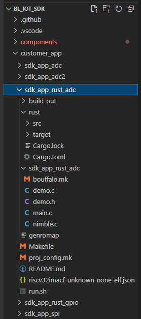
}Before diving into the Rust Firmware, let's walk through the steps for creating a BL602 Rust Project (like sdk_app_rust_adc)...
-
Download the Source Code for BL602 IoT SDK...
git clone --recursive https://github.com/lupyuen/bl_iot_sdk
-
Copy the Project Folder for an existing Rust Project in
bl_iot_sdk/customer_app, likesdk_app_rust_gpio... -
Paste the Project Folder into
bl_iot_sdk/customer_appand rename it (likesdk_app_rust_adc)...Be sure to rename the Sub Folder too. (The
sdk_app_rust_adcinsidesdk_app_rust_adc)Delete the
build_outfolder if it exists. -
Edit the
Makefilein the new folder and set the Project Name:sdk_app_rust_adc/Makefile## Set the project name PROJECT_NAME := sdk_app_rust_adc -
Set the GCC Compiler Options (if any) in the Makefile
sdk_app_rust_adc / sdk_app_rust_adc / bouffalo.mk -
Edit the
run.shscript in the new folder and set the Project Name:sdk_app_rust_adc/run.sh## Set the project name export APP_NAME=sdk_app_rust_adc
-
Replace the Rust Source Code in
sdk_app_rust_adc/ rust/src/lib.rs -
See the Appendix for the steps to define the Rust Commands for the Command-Line Interface in
sdk_app_rust_adc / demo.c -
Remember to edit
README.mdand fill in the project details
Now we study the Rust Firmware for BL602 ADC: sdk_app_rust_adc
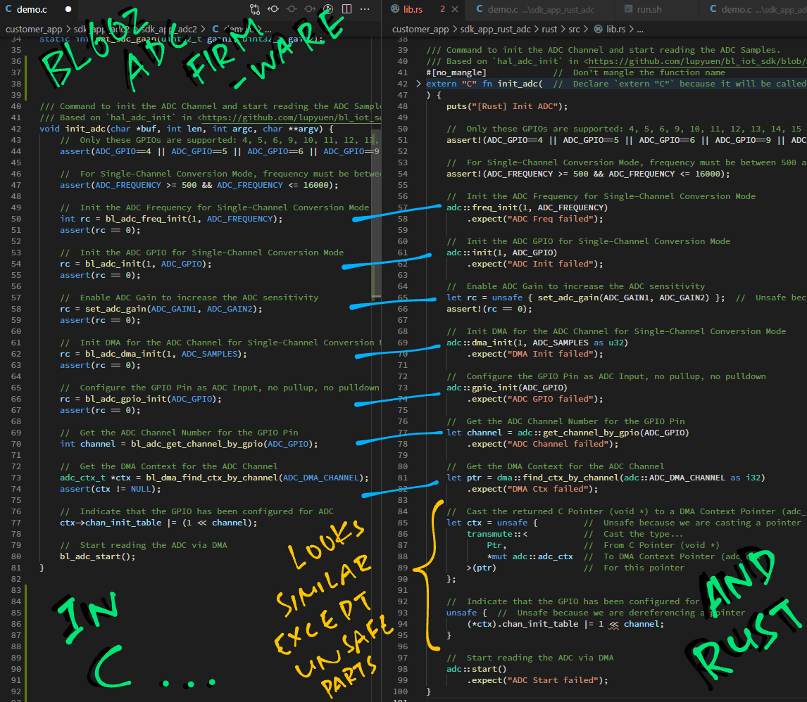
We have converted the C Firmware to Rust line by line, so the Rust code will look highly similar to C.
Recall that our firmware implements two commands...
-
Initialise the ADC Channel for reading our LED GPIO
-
Compute the average value of the ADC Samples that have been read
Here is the Rust implementation...
We start by declaring to the Rust Compiler that we're calling the Rust Core Library (instead of Rust Standard Library): lib.rs
#![no_std] // Use the Rust Core Library instead of the Rust Standard Library, which is not compatible with embedded systems(Rust Standard Library is too heavy for embedded programs)
Next we import the functions from Rust Core Library that will be used in a while...
//  Import Libraries
use core::{          //  Rust Core Library
  fmt::Write,        //  String Formatting
  mem::transmute,    //  Pointer Casting
  panic::PanicInfo,  //  Panic Handler
};
We import the Rust Wrapper for BL602 IoT SDK...
use bl602_sdk::{     //  Rust Wrapper for BL602 IoT SDK
  adc,               //  ADC HAL
  dma,               //  DMA HAL
  puts,              //  Console Output
  Ptr,               //  C Pointer
  String,            //  Strings (limited to 64 chars)
};
We shall read GPIO 11 (the Blue LED) as ADC Input...
/// GPIO Pin Number that will be configured as ADC Input.
/// PineCone Blue LED is connected on BL602 GPIO 11.
/// PineCone Green LED is connected on BL602 GPIO 14.
/// Only these GPIOs are supported: 4, 5, 6, 9, 10, 11, 12, 13, 14, 15
/// TODO: Change the GPIO Pin Number for your BL602 board
const ADC_GPIO: i32 = 11;
BL602 ADC Controller shall read 10,000 ADC Samples per second, and remember the last 100 ADC Samples...
/// We set the ADC Frequency to 10 kHz according to <https://wiki.analog.com/university/courses/electronics/electronics-lab-led-sensor?rev=1551786227>
/// This is 10,000 samples per second.
const ADC_FREQUENCY: u32 = 10000;  //  Hz

/// We shall read 100 ADC samples, which will take 0.01 seconds
const ADC_SAMPLES: usize = 100;(usize is similar to size_t in C, it's used to represent the size of arrays)
We shall set the ADC Gain to increase the ADC sensitivity...
/// Set ADC Gain to Level 1 to increase the ADC sensitivity.
/// To disable ADC Gain, set `ADC_GAIN1` and `ADC_GAIN2` to `ADC_PGA_GAIN_NONE`.
/// See <https://github.com/lupyuen/bl_iot_sdk/blob/master/components/bl602/bl602_std/bl602_std/StdDriver/Inc/bl602_adc.h#L133-L144>
const ADC_GAIN1: u32 = ADC_PGA_GAIN_1;
const ADC_GAIN2: u32 = ADC_PGA_GAIN_1;
But ADC_PGA_GAIN_1 is missing from our Rust Wrapper.
Thus we copy the value from BL602 IoT SDK and define it here...
const ADC_PGA_GAIN_1: u32 = 1; // From <https://github.com/lupyuen/bl_iot_sdk/blob/master/components/bl602/bl602_std/bl602_std/StdDriver/Inc/bl602_adc.h#L133-L144>Here's our Rust Function init_adc that will be called by the BL602 Command-Line Interface: lib.rs
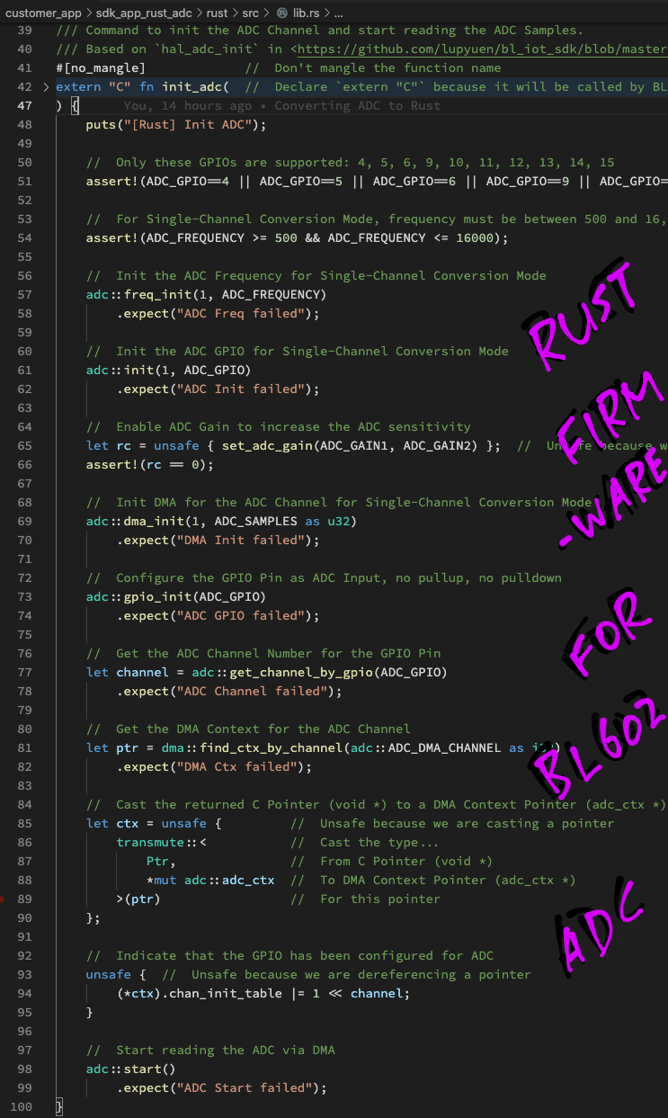
/// Command to init the ADC Channel and start reading the ADC Samples.
/// Based on `hal_adc_init` in <https://github.com/lupyuen/bl_iot_sdk/blob/master/components/hal_drv/bl602_hal/hal_adc.c#L50-L102>
#[no_mangle]             //  Don't mangle the function name
extern "C" fn init_adc(  //  Declare `extern "C"` because it will be called by BL602 firmware
  _result: *mut u8,        //  Result to be returned to command-line interface (char *)
  _len:  i32,              //  Size of result buffer (int)
  _argc: i32,              //  Number of command line args (int)
  _argv: *const *const u8  //  Array of command line args (char **)
) {
  puts("[Rust] Init ADC");
(We won't be parsing the command-line arguments, so let's ignore the parameters passed to init_adc)
We start by validating the GPIO Pin Number and ADC Frequency...
  //  Only these GPIOs are supported: 4, 5, 6, 9, 10, 11, 12, 13, 14, 15
  assert!(ADC_GPIO==4 || ADC_GPIO==5 || ADC_GPIO==6 || ADC_GPIO==9 || ADC_GPIO==10 || ADC_GPIO==11 || ADC_GPIO==12 || ADC_GPIO==13 || ADC_GPIO==14 || ADC_GPIO==15);

  //  For Single-Channel Conversion Mode, frequency must be between 500 and 16,000 Hz
  assert!(ADC_FREQUENCY >= 500 && ADC_FREQUENCY <= 16000);
(Remember: Not all GPIOs are supported for ADC!)
Next we select ADC Mode 1 (Single-Channel Conversion) and set the ADC Frequency...
  //  Init the ADC Frequency for Single-Channel Conversion Mode
  adc::freq_init(1, ADC_FREQUENCY)
    .expect("ADC Freq failed");
We set the ADC GPIO Pin Number for ADC Mode 1...
  //  Init the ADC GPIO for Single-Channel Conversion Mode
  adc::init(1, ADC_GPIO)
    .expect("ADC Init failed");
To increase the ADC sensitivity, we set the ADC Gain...
  //  Enable ADC Gain to increase the ADC sensitivity
  let rc = unsafe { set_adc_gain(ADC_GAIN1, ADC_GAIN2) };  //  Unsafe because we are calling C function
  assert!(rc == 0);
(This calls our C function set_adc_gain, which shall be explained below)
BL602 ADC Controller shall transfer the ADC Samples directly into RAM, thanks to the Direct Memory Access (DMA) Controller...
  //  Init DMA for the ADC Channel for Single-Channel Conversion Mode
  adc::dma_init(1, ADC_SAMPLES as u32)
    .expect("DMA Init failed");
(First parameter of dma_init is the ADC Mode)
We configure the GPIO Pin for ADC Input...
  //  Configure the GPIO Pin as ADC Input, no pullup, no pulldown
  adc::gpio_init(ADC_GPIO)
    .expect("ADC GPIO failed");
And we fetch the DMA Context for the ADC Channel...
  //  Get the ADC Channel Number for the GPIO Pin
  let channel = adc::get_channel_by_gpio(ADC_GPIO)
    .expect("ADC Channel failed");

  //  Get the DMA Context for the ADC Channel
  let ptr = dma::find_ctx_by_channel(adc::ADC_DMA_CHANNEL as i32)
    .expect("DMA Ctx failed");
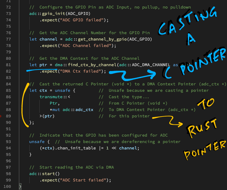
However the returned pointer ptr is actually a "void *" pointer from C.
To use the pointer in Rust, we cast it to a DMA Context Pointer...
  //  Cast the returned C Pointer (void *) to a DMA Context Pointer (adc_ctx *)
  let ctx = unsafe {     //  Unsafe because we are casting a pointer
    transmute::<         //  Cast the type...
      Ptr,               //  From C Pointer (void *)
      *mut adc::adc_ctx  //  To DMA Context Pointer (adc_ctx *)
    >(ptr)               //  For this pointer
  };
(More about transmute in the Appendix)
Now we may update the DMA Context for the ADC Channel...
  //  Indicate that the GPIO has been configured for ADC
  unsafe {  //  Unsafe because we are dereferencing a pointer
    (*ctx).chan_init_table |= 1 << channel;
  }
(We flag this as unsafe because we're dereferencing a pointer: ctx)
Finally we start the ADC Channel...
  //  Start reading the ADC via DMA
  adc::start()
    .expect("ADC Start failed");
}
BL602 ADC Controller will read the ADC Samples continuously (from the GPIO Pin) into RAM (until we stop the ADC Channel).
Our ADC Channel has been started, how do we average the ADC Samples that have been read?
Let's check out the Rust Function read_adc in lib.rs ...
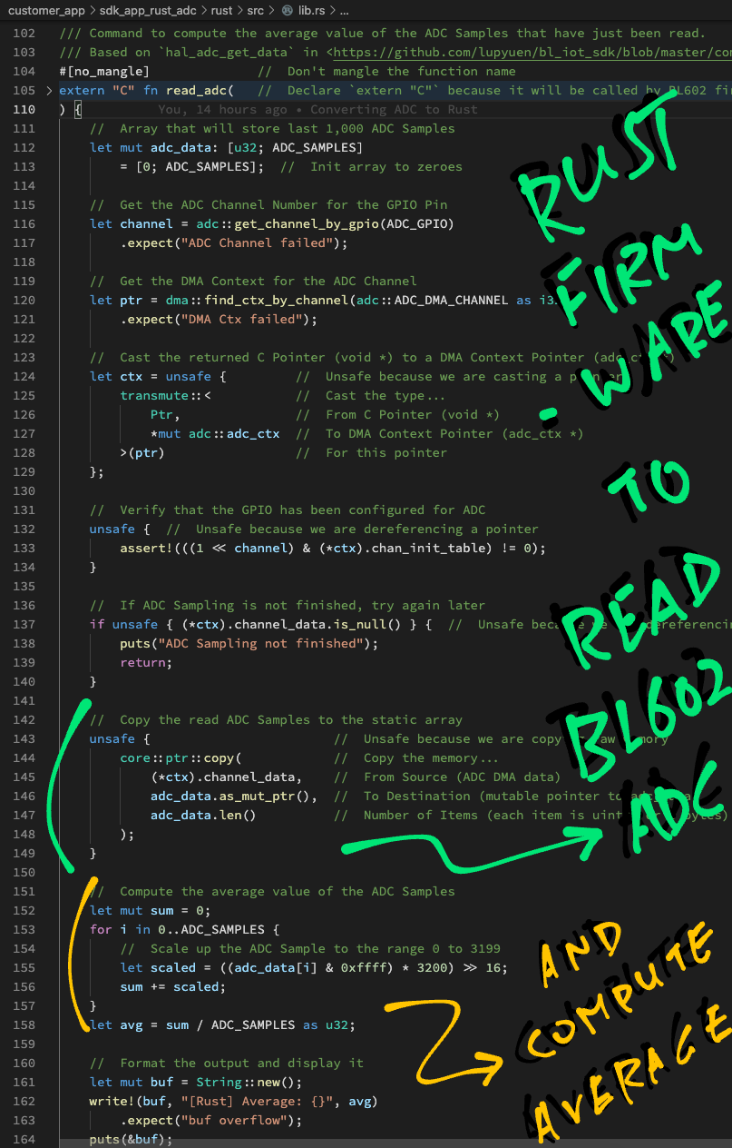
/// Command to compute the average value of the ADC Samples that have just been read.
/// Based on `hal_adc_get_data` in <https://github.com/lupyuen/bl_iot_sdk/blob/master/components/hal_drv/bl602_hal/hal_adc.c#L142-L179>
#[no_mangle]              //  Don't mangle the function name
extern "C" fn read_adc(   //  Declare `extern "C"` because it will be called by BL602 firmware
  _result: *mut u8,        //  Result to be returned to command-line interface (char *)
  _len:  i32,              //  Size of result buffer (int)
  _argc: i32,              //  Number of command line args (int)
  _argv: *const *const u8  //  Array of command line args (char **)
) {
First we fetch the DMA Context for the ADC Channel...
  //  Get the ADC Channel Number for the GPIO Pin
  let channel = adc::get_channel_by_gpio(ADC_GPIO)
    .expect("ADC Channel failed");

  //  Get the DMA Context for the ADC Channel
  let ptr = dma::find_ctx_by_channel(adc::ADC_DMA_CHANNEL as i32)
    .expect("DMA Ctx failed");
Again we cast the returned C pointer ptr to a DMA Context Pointer...
  //  Cast the returned C Pointer (void *) to a DMA Context Pointer (adc_ctx *)
  let ctx = unsafe {     //  Unsafe because we are casting a pointer
    transmute::<         //  Cast the type...
      Ptr,               //  From C Pointer (void *)
      *mut adc::adc_ctx  //  To DMA Context Pointer (adc_ctx *)
    >(ptr)               //  For this pointer
  };
(More about transmute in the Appendix)
Now we may verify the DMA Context for the ADC Channel...
  //  Verify that the GPIO has been configured for ADC
  unsafe {  //  Unsafe because we are dereferencing a pointer
    assert!(((1 << channel) & (*ctx).chan_init_table) != 0);
  }
(We flag this as unsafe because we're dereferencing a pointer: ctx)
And we check whether the ADC Sampling has been completed for the ADC Channel (channel_data shouldn't be null)...
  //  If ADC Sampling is not finished, try again later
  if unsafe { (*ctx).channel_data.is_null() } {  //  Unsafe because we are dereferencing a pointer
    puts("ADC Sampling not finished");
    return;
  }
(Again we flag as unsafe because we're dereferencing the pointer ctx)
Remember that the BL602 ADC Controller will read ADC Samples continuously and write the last 100 samples to RAM (via DMA).
We define an array adc_data to store the last 100 samples temporarily (on the stack)...
  //  Array that will store the last 100 ADC Samples
  //  (`ADC_SAMPLES` is 100)
  let mut adc_data: [u32; ADC_SAMPLES]
    = [0; ADC_SAMPLES];  //  Init array to 100 zeroes
(Rust requires all variables to be initialised, so we set the array to 100 zeroes)
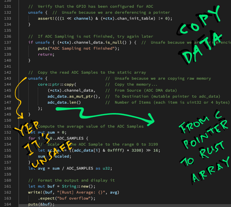
Let's copy the last 100 ADC Samples from the DMA Context (in RAM) to our array adc_data (on the stack)...
  //  Copy the read ADC Samples to the array
  unsafe {                    //  Unsafe because we are copying raw memory
    core::ptr::copy(          //  Copy the memory...
      (*ctx).channel_data,    //  From Source (ADC DMA data)
      adc_data.as_mut_ptr(),  //  To Destination (mutable pointer to adc_data)
      adc_data.len()          //  Number of Items (each item is uint32 or 4 bytes)
    );
  }
(More about this in the Appendix)
(adc_data.len() returns the array length: 100)
Then we compute the average value of the ADC Samples in adc_data...
  //  Compute the average value of the ADC Samples
  let mut sum = 0;
  for i in 0..ADC_SAMPLES {  //  From 0 to 99, `..` excludes 100
    //  Scale up the ADC Sample to the range 0 to 3199
    let scaled = ((adc_data[i] & 0xffff) * 3200) >> 16;
    sum += scaled;
  }
  let avg = sum / ADC_SAMPLES as u32;
We scale each ADC Sample to the range 0 to 3199. (Because the default ADC Configuration produces 12-bit samples)
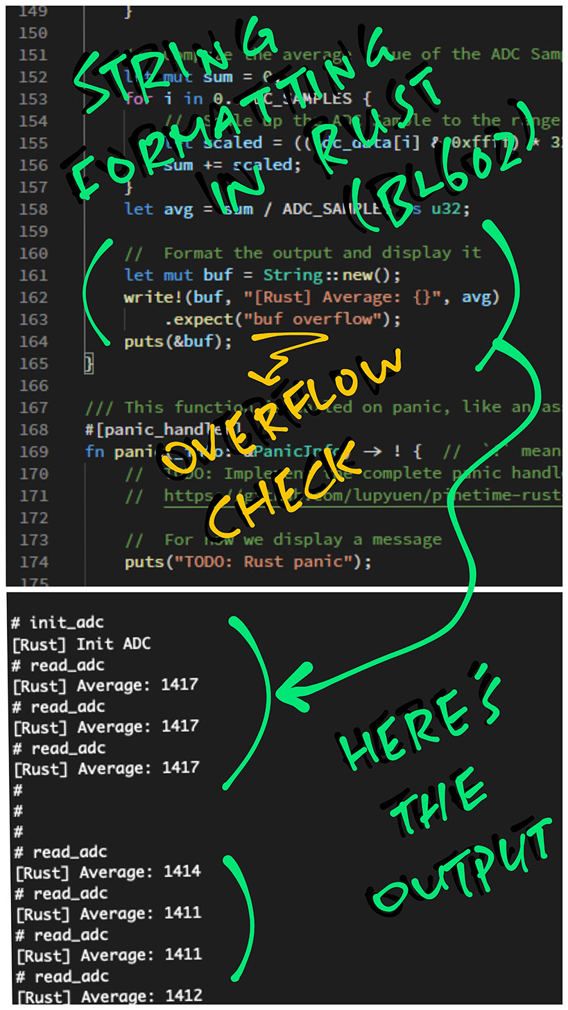
Finally we compose a formatted string with the average value and display it...
  //  Format the output
  let mut buf = String::new();
  write!(buf, "[Rust] Average: {}", avg)
    .expect("buf overflow");

  //  Display the formatted output
  puts(&buf);
}
(Yep Rust will helpfully check for buffer overflow... safer than sprintf!)
Default String Size is 64 characters, as defined in the BL602 Rust Wrapper.
(Similar to "char[64]" in C)
The formatted output will appear like so...
And we're done... That's how we code BL602 ADC Firmware in Rust!
We may download the Rust Firmware Binary File sdk_app_rust_adc.bin from...
Or follow these steps to build the Rust Firmware sdk_app_rust_adc.bin...
-
Install
rustup,blflashandxpack-riscv-none-embed-gcc -
Download the source code for the BL602 Rust Firmware...
## Download the master branch of lupyuen's bl_iot_sdk
git clone --recursive --branch master https://github.com/lupyuen/bl_iot_sdk
cd bl_iot_sdk/customer_app/sdk_app_rust_adc
-
Edit the script
run.shin thesdk_app_rust_adcfolder.This build script was created for macOS, but can be modified to run on Linux x64 and Windows WSL.
-
In
run.sh, set the following variables to the downloaded folders forblflashandxpack-riscv-none-embed-gcc...## Where blflash is located export BLFLASH_PATH=$PWD/../../../blflash ## Where GCC is located export GCC_PATH=$PWD/../../../xpack-riscv-none-embed-gcc
Save the changes into
run.sh -
Build the firmware...
./run.sh
-
We should see...
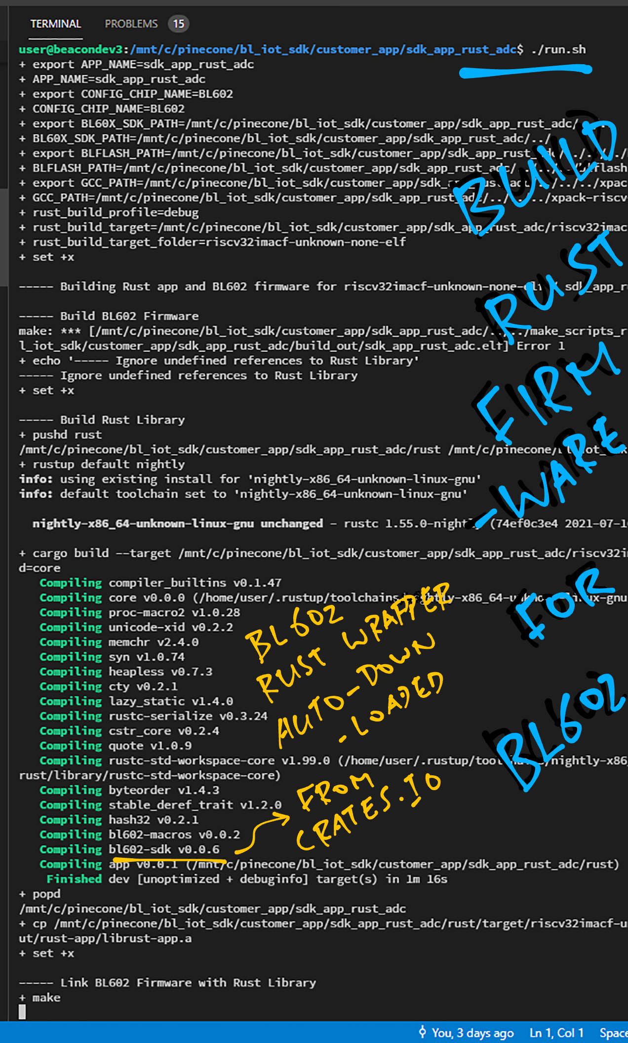
----- Building Rust app and BL602 firmware for riscv32imacf-unknown-none-elf / sdk_app_rust_adc...

----- Build BL602 Firmware
+ make
...
LD build_out/sdk_app_rust_adc.elf
ld: undefined reference to `init_adc'
ld: undefined reference to `read_adc'
----- Ignore undefined references to Rust Library
This means that the C code from our BL602 Firmware has been built successfully.
-
Next the script compiles our Rust code into a static library:
libapp.a----- Build Rust Library + rustup default nightly + cargo build \ --target ../riscv32imacf-unknown-none-elf.json \ -Z build-std=core Updating crates.io index Compiling compiler_builtins v0.1.46 Compiling core v0.0.0 ... Compiling bl602-macros v0.0.2 Compiling bl602-sdk v0.0.6 Compiling app v0.0.1 (bl_iot_sdk/customer_app/sdk_app_rust_adc/rust) Finished dev [unoptimized + debuginfo] target(s) in 23.55s -
Finally the script links the Rust static library into our BL602 firmware...
----- Link BL602 Firmware with Rust Library
+ make
use existing version.txt file
LD build_out/sdk_app_rust_adc.elf
Generating BIN File to build_out/sdk_app_rust_adc.bin
...
Building Finish. To flash build output.
Ignore the error from
blflash, we'll fix this in a while. -
Our BL602 Rust Firmware file has been generated at...
build_out/sdk_app_rust_adc.binLet's flash this to BL602 and run it!
Check out the complete build log here...
More about the custom Rust target
Here's how we flash the Rust Firmware file sdk_app_rust_adc.bin to BL602...
-
Set BL602 to Flashing Mode and restart the board...
For PineCone:
-
Set the PineCone Jumper (IO 8) to the
HPosition (Like this) -
Press the Reset Button
For BL10:
-
Connect BL10 to the USB port
-
Press and hold the D8 Button (GPIO 8)
-
Press and release the EN Button (Reset)
-
Release the D8 Button
For Ai-Thinker Ai-WB2, Pinenut and MagicHome BL602:
-
Disconnect the board from the USB Port
-
Connect GPIO 8 to 3.3V
-
Reconnect the board to the USB port
-
-
For macOS:
Enter this at the command prompt...
./run.sh
The script should automatically flash the firmware after building...
----- Flash BL602 Firmware

+ blflash flash build_out/sdk_app_rust_adc.bin \
    --port /dev/tty.usbserial-1410 \
    --initial-baud-rate 230400 \
    --baud-rate 230400

Finished dev [unoptimized + debuginfo] target(s) in 0.61s
Running `target/debug/blflash flash sdk_app_rust_adc.bin --port /dev/tty.usbserial-1420 --initial-baud-rate 230400 --baud-rate 230400`
Start connection...
5ms send count 115
handshake sent elapsed 104.593µs
Connection Succeed
Bootrom version: 1
Boot info: BootInfo { len: 14, bootrom_version: 1, otp_info: [0, 0, 0, 0, 3, 0, 0, 0, 61, 9d, c0, 5, b9, 18, 1d, 0] }
Sending eflash_loader...
Finished 1.595620342s 17.92KB/s
5ms send count 115
handshake sent elapsed 81.908µs
Entered eflash_loader
Skip segment addr: 0 size: 47504 sha256 matches
Skip segment addr: e000 size: 272 sha256 matches
Skip segment addr: f000 size: 272 sha256 matches
Erase flash addr: 10000 size: 135808
Program flash... ed8a4cdacbc4c1543c74584d7297ad876b6731104856a10dff4166c123c6637d
Program done 7.40735771s 17.91KB/s
Skip segment addr: 1f8000 size: 5671 sha256 matches
Success
(We might need to edit the script to use the right serial port)
-
For Linux and Windows:
Copy
build_out/sdk_app_rust_adc.binto theblflashfolder.Then enter this at the command prompt...
## TODO: Change this to the downloaded blflash folder
cd blflash

## For Linux:
blflash flash build_out/sdk_app_lora.bin \
    --port /dev/ttyUSB0

## For Windows: Change COM5 to the BL602 Serial Port
blflash flash c:\blflash\sdk_app_lora.bin --port COM5
More details on flashing firmware
Finally we run the BL602 Rust Firmware...
-
Set BL602 to Normal Mode (Non-Flashing) and restart the board...
For PineCone:
-
Set the PineCone Jumper (IO 8) to the
LPosition (Like this) -
Press the Reset Button
For BL10:
- Press and release the EN Button (Reset)
For Ai-Thinker Ai-WB2, Pinenut and MagicHome BL602:
-
Disconnect the board from the USB Port
-
Connect GPIO 8 to GND
-
Reconnect the board to the USB port
-
-
For macOS:
The
run.shscript should automatically launch CoolTerm after flashing...----- Run BL602 Firmware + open -a CoolTermFor Linux:
Connect to BL602's UART Port at 2 Mbps like so...
screen /dev/ttyUSB0 2000000
For Windows:
Use
putty(See this)Alternatively:
Use the Web Serial Terminal (See this)
-
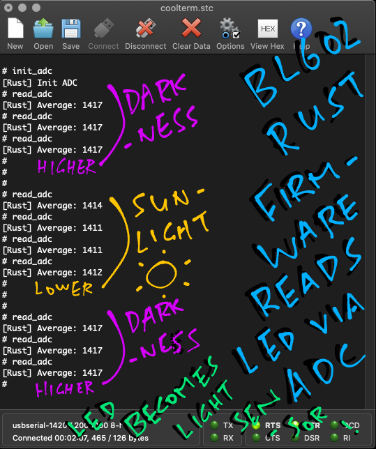
In the serial console, enter the
init_adccommand to initialise the ADC Channel...init_adc [Rust] Init ADC(We've seen this function earlier)
-
Place the BL602 Board (with LED) in a dark place.
-
Enter the
read_adccommand a few times to get the average values of the last 1,000 ADC Samples...read_adc [Rust] Average: 1417 read_adc [Rust] Average: 1417 read_adc [Rust] Average: 1417 -
Now place the BL602 Board (with LED) under sunlight.
-
Enter the
read_adccommand a few times...read_adc [Rust] Average: 1411 read_adc [Rust] Average: 1411 read_adc [Rust] Average: 1412Note that the average values have dropped from 1417 to 1412.
-
Place the BL602 Board (with LED) back in the dark and check the average values...
read_adc [Rust] Average: 1417 read_adc [Rust] Average: 1417 read_adc [Rust] Average: 1417The average values have increased from 1412 to 1417.
Our improvised BL602 Light Sensor works in Rust yay!
I'm new to Rust. Is there an easier way to jump from C to Rust?
Today we've seen that it's feasible to translate C Firmware into Rust line by line...
Which is great for embedded developers new to Rust!
Just be mindful of the differences between C and Rust...
-
BL602 HAL Functions have been renamed for Rust.
(Like "
bl_adc_init" becomes "adc::init")To see the list of BL602 HAL Functions for Rust, check out the
bl602-sdkdocumentation.(More about this in the next chapter)
-
In Rust we check for BL602 HAL Errors by calling "
expect" instead of "assert".(Rust Compiler will warn us if we forget to "
expect") -
Rust is super strict about Mutability... Only variables and pointers declared "
mut" can be changed.(That's why we write "
*mut i32" to get a pointer to an integer whose value may be changed) -
Pointer Deferencing like "
ptr->field" doesn't work in Rust.We rewrite it in Rust as "
(*ptr).field" -
Rust will helpfully check for Buffer Overflow.
(No more silent "
sprintf" overflow!)For BL602 Rust Wrapper the default string size is 64 characters.
(Similar to "
char[64]" in C) -
All Rust variables shall be initialised before use.
(Even arrays and structs!)
Let's talk about "unsafe" code in Rust...
Rust reminds us to be Extra Careful when we work with C Functions and C Pointers.
That's why we need to flag the following code as unsafe...
-
Calling C Functions
//  Call the C function `set_adc_gain`
unsafe { set_adc_gain(ADC_GAIN1, ADC_GAIN2) };
(More about this in the Appendix)
-
Casting C Pointers to Rust
//  Cast a C Pointer to a Rust Pointer
let ctx = unsafe {
  transmute::<         //  Cast the type...
    Ptr,               //  From C Pointer (void *)
    *mut adc::adc_ctx  //  To DMA Context Pointer (adc_ctx *)
  >(ptr)               //  For this pointer
};
(More about this in the Appendix)
-
Dereferencing C Pointers
//  Dereference a C Pointer (ctx)
unsafe {
  (*ctx).chan_init_table = ...
}
-
Copying Memory with C Pointers
//  Copy memory with a C Pointer (channel_data)
unsafe {
  core::ptr::copy(          //  Copy the memory...
    (*ctx).channel_data,    //  From Source (ADC DMA data)
    adc_data.as_mut_ptr(),  //  To Destination (mutable pointer to adc_data)
    adc_data.len()          //  Number of Items (each item is uint32 or 4 bytes)
  );
}
(More about this in the Appendix)
Accessing Static Variables is also "unsafe". Let's talk about this...
Earlier we saw this Rust code for averaging the ADC Samples...
//  `adc_data` will store 100 ADC Samples (`ADC_SAMPLES` is 100)
let mut adc_data: [u32; ADC_SAMPLES] = [0; ADC_SAMPLES];

//  Omitted: Copy data into `adc_data`
...

//  Compute average of `adc_data`
for i in 0..ADC_SAMPLES {
  //  Get value from `adc_data`
  let scaled = adc_data[i] & ...
Note that adc_data lives on the stack.
That's a huge chunk of data on the stack... 400 bytes!
What if we turn adc_data into a Static Array?
We convert adc_data to a Static Array like this...
//  `adc_data` becomes a Static Array
static mut adc_data: [u32; ADC_SAMPLES] = [0; ADC_SAMPLES];
adc_data no longer lives on the stack, it's now in Static Memory.
What's the catch?
Unfortunately Static Variables in Rust are unsafe.
Thus all references to adc_data must be flagged as unsafe...
//  `adc_data` is now unsafe because it's a Static Variable
let scaled = unsafe { adc_data[i] } & ...
Which makes the code harder to read. That's why we left adc_data on the stack for this tutorial.
Why are Static Variables unsafe?
Because it's potentially possible to execute the above code in multiple tasks...
Which produces undefined behaviour when multiple tasks access the same Static Variable.
So it's perfectly OK to use Static Variables in Rust. Just that we need to...
-
Flag the Static Variables as
unsafe -
Ensure ourselves that Static Variables are only accessed by one task at a time
The BL602 Rust Wrapper Functions look mighty similar to the C Functions from the BL602 IoT SDK. How is this possible?
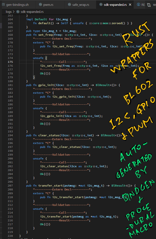
Because the Rust Functions were automatically generated from BL602 IoT SDK!
We ran a script to generate the Rust Wrapper for BL602 IoT SDK.
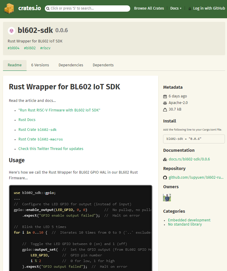
And we published the Rust Wrapper on crates.io...
Which functions from the BL602 IoT SDK are supported?
Today our BL602 Rust Wrapper supports...
| ◾ ADC | ◾ I2C | ◾ UART |
| ◾ DMA | ◾ PWM | ◾ WiFi |
| ◾ GPIO | ◾ SPI |
How do we add the BL602 Rust Wrapper to our Rust Project?
Just add bl602-sdk to the Rust project configuration: rust/Cargo.toml
## External Rust libraries used by this module.  See crates.io.
[dependencies]
bl602-sdk = "0.0.6"  # Rust Wrapper for BL602 IoT SDK: https://crates.io/crates/bl602-sdk
(Change "0.0.6" to the latest version on crates.io)
The BL602 Rust Wrapper will be auto-downloaded from crates.io when building the project.
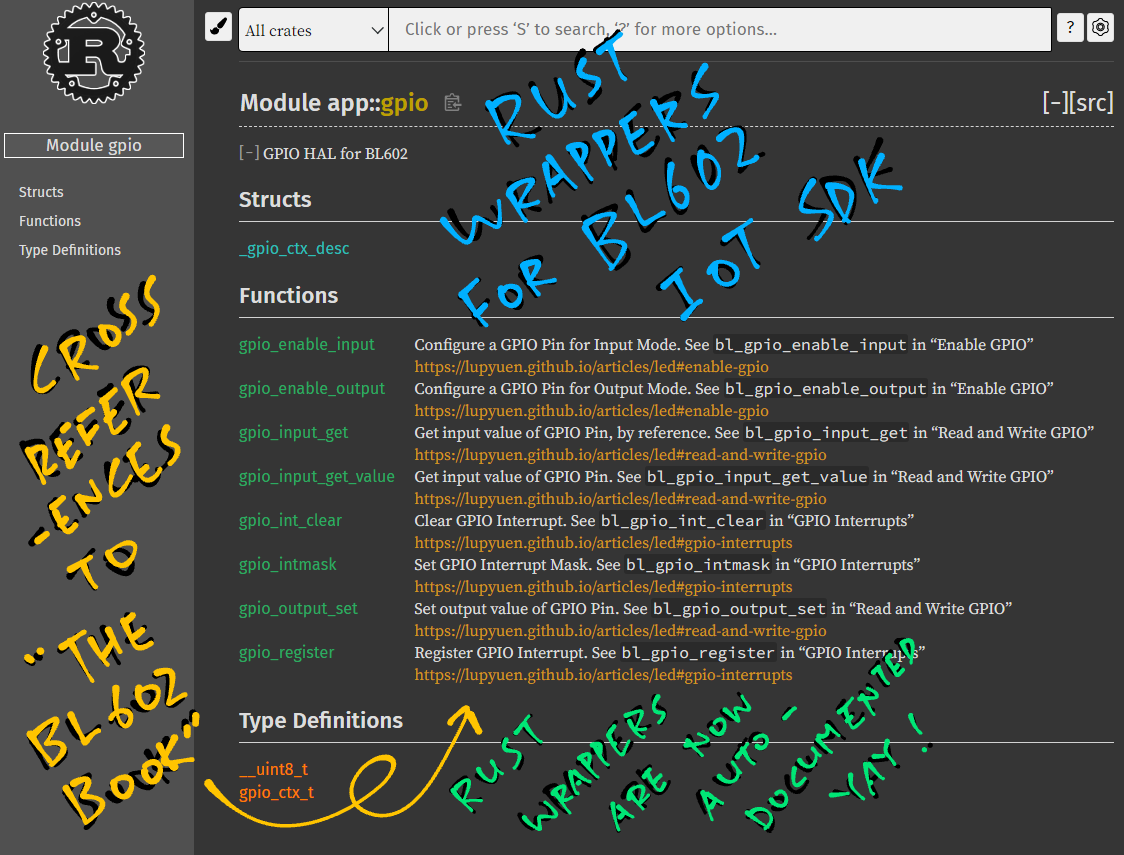
Is the BL602 Rust Wrapper documented?
Yep! Every Rust Function is linked to the section in "The RISC-V BL602 Book" that explains how we call the function...
(Check the Appendix to learn more about the BL602 Rust Wrapper)
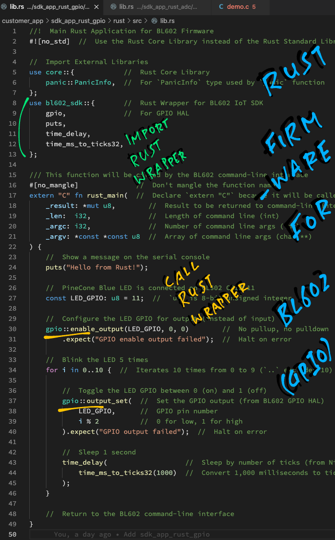
Here's a sample project that calls the Rust Wrapper for GPIO...
Why does our BL602 LED detect only sunlight? And not other kinds of light?
We're guessing because...
-
Sunlight is more intense
(And produces more current)
-
We used the Blue LED on PineCone BL602
(Which is sensitive to the spectrum of Blue - Indigo - Violet - Ultra-Violet (UV) light)
LED Light Sensitivity is explained in this article...
As a photodiode, an LED is sensitive to wavelengths equal to or shorter than the predominant wavelength it emits. A green LED would be sensitive to blue light and to some green light, but not to yellow or red light.
Also according to Sravan Senthilnathan on Twitter...
This is possible due to the blue LED's semiconductor bandgap being one appropriate to absorb the UV spectrum sun light. Here is more info about it: Aluminium gallium nitride on Wikipedia
And according to Dan Lafleur on LinkedIn...
The technique I used to measure light level with an LED was to reverse bias the LED and then time the discharge. The light level is time based. The higher the light level the longer it takes to discharge the reversed bias junction.
(More about measuring the Discharge Duration of an LED)
Here's another comment...
Yes, I have used LEDs as light sensors in class projects. The point is that they are not just emitters. A selection of red, green and blue LEDs can be used to build a crude colour detector. It works.
That sounds interesting...
PineCone BL602 has Red, Green and Blue LEDs. Can we use the other LEDs?
(From PineCone BL602 Schematic)
Unfortunately PineCone's Red LED is connected on GPIO 17, which is not supported for ADC.
But PineCone's Green LED (GPIO 14) should work OK with ADC.
Exercise For The Reader: Use PineCone's Green LED (instead of the Blue LED) as an ADC Light Sensor. What kind of light does it detect?
(This article was inspired by the BBC micro:bit, which uses LED as a Light Sensor. See this)
Testing the improvised Light Sensor on PineCone BL602 with Pinebook Pro
Today we've seen that it's viable to create Rust Firmware for BL602... Just call the Rust Wrapper for BL602 IoT SDK!
Soon we shall test the Rust Firmware on PineDio Stack BL604 with LoRa SX1262... As we explore whether it's feasible to teach Rust as a Safer Way to create firmware for BL602 and BL604.
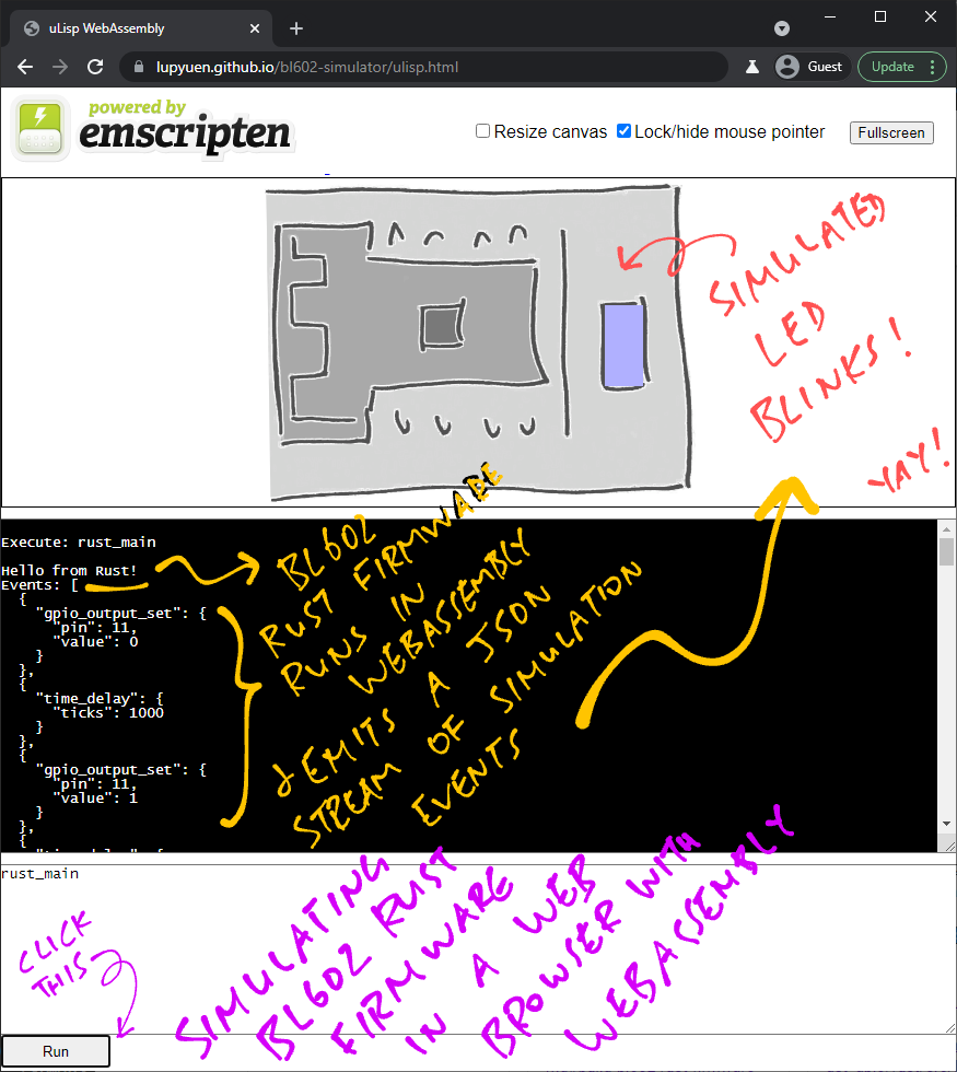
Also we might Simulate BL602 Rust Firmware in a Web Browser with WebAssembly!
Many Thanks to my GitHub Sponsors for supporting my work! This article wouldn't have been possible without your support.
Got a question, comment or suggestion? Create an Issue or submit a Pull Request here...
-
This article is the expanded version of this Twitter Thread on Rust Wrapper for BL602 IoT SDK
-
Are there other ways to run Rust Firmware on BL602? See this...
-
We may also use BL602 ADC HAL to read the BL602 Internal Temperature Sensor...
-
Is there a simpler way to code ADC Firmware in C?
Yes, we could call the ADC High Level HAL.
(Instead of the ADC Low Level HAL that we've seen)
Here's our ADC Firmware, rewritten to call the ADC High Level HAL...
But the ADC High Level HAL won't let us set the ADC Gain.
We need to patch the ADC Low Level HAL like so...
Also note that the ADC High Level HAL doesn't allow us to compute the average of the ADC Samples.
It returns only one ADC Sample.
-
ESP32 has something similar to the BL602 Rust Wrapper...
-
esp-idf-sysdefines the Rust Bindings for ESP32 IDF SDK (generated withbindgen) -
esp-idf-halwrapsesp-idf-sysinto a Rust Embedded HAL for ESP32
(Perhaps someday we might wrap the BL602 Rust Wrapper into a Rust Embedded HAL for BL602 / BL604)
-
How do we call our own C Functions from Rust?
Earlier we saw this Rust code that sets the ADC Gain: lib.rs
//  In Rust: Enable ADC Gain to increase the ADC sensitivity
unsafe { set_adc_gain(ADC_GAIN1, ADC_GAIN2) };  //  Unsafe because we are calling C function
This calls the C Function set_adc_gain, which we have imported into Rust here: lib.rs
//  In Rust: Import C Function
extern "C" {
  /// Enable ADC Gain to increase the ADC sensitivity.
  /// Defined in customer_app/sdk_app_rust_adc/sdk_app_rust_adc/demo.c
  fn set_adc_gain(gain1: u32, gain2: u32) -> i32;
}
set_adc_gain is defined in this C source file: demo.c
What about the rest of the code in demo.c?
The rest of the C code in demo.c is needed to set up the Command-Line Interface for our BL602 Firmware.
We define the Rust Commands for the Command-Line Interface like so: demo.c
/// In C: Import Rust functions from customer_app/sdk_app_rust_adc/rust/src/lib.rs
void init_adc(char *buf, int len, int argc, char **argv);
void read_adc(char *buf, int len, int argc, char **argv);

/// List of commands. STATIC_CLI_CMD_ATTRIBUTE makes these commands static
const static struct cli_command cmds_user[] STATIC_CLI_CMD_ATTRIBUTE = {
    {"init_adc",        "Init ADC Channel",          init_adc},
    {"read_adc",        "Read ADC Channel",          read_adc},
};
This defines the commands init_adc and read_adc, which are mapped to the respective Rust Functions.
How do we cast C Pointers in Rust?
In the C version of our ADC Firmware, we implicitly cast a "void *" pointer to "adc_ctx *" pointer like this: demo.c
//  In C: Get the pointer (void *) for DMA Context
void *ptr = ...

//  Cast the returned pointer (void *) to a DMA Context Pointer (adc_ctx *)
struct adc_ctx *ctx = (struct adc_ctx *) ptr;
Here we're Downcasting a General Type (void *) to a Specific Type (adc_ctx *).
To do the same in Rust, we need to be super explicit about what we're casting: lib.rs
//  In Rust: Get the C Pointer (void *) for DMA Context
let ptr = ...

//  Cast the returned C Pointer (void *) to a DMA Context Pointer (adc_ctx *)
let ctx = unsafe {     //  Unsafe because we are casting a pointer
  transmute::<         //  Cast the type...
    Ptr,               //  From C Pointer (void *)
    *mut adc::adc_ctx  //  To DMA Context Pointer (adc_ctx *)
  >(ptr)               //  For this pointer
};
transmute is the Rust Core Library Function that will cast our value (ptr) from one type to another...
transmute::< FromType , ToType >( ptr )Where...
-
From Type is
PtrPtris our short form for the "void *" pointer in Rust. -
To Type is
*mut adc::adc_ctxWhich is a mutable pointer to
adc_ctx(Equivalent to "
adc_ctx *" in C)
How do we copy memory with C Pointers?
Earlier we saw this code in our C Firmware: demo.c
//  Array that will store ADC Samples
uint32_t adc_data[ADC_SAMPLES];

//  Copy the read ADC Samples to the array
memcpy(
  (uint8_t*) adc_data,             //  Destination
  (uint8_t*) (ctx->channel_data),  //  Source
  sizeof(adc_data)                 //  Size
);
This code copies the ADC Samples from the DMA buffer to the array adc_data.
Here's the equivalent code in Rust: lib.rs
//  Array that will store the last 100 ADC Samples (`ADC_SAMPLES` is 100)
let mut adc_data: [u32; ADC_SAMPLES]
  = [0; ADC_SAMPLES];  //  Init array to 100 zeroes

//  Copy the read ADC Samples to the array
unsafe {                    //  Unsafe because we are copying raw memory
  core::ptr::copy(          //  Copy the memory...
    (*ctx).channel_data,    //  From Source (ADC DMA data)
    adc_data.as_mut_ptr(),  //  To Destination (mutable pointer to adc_data)
    adc_data.len()          //  Number of Items (each item is uint32 or 4 bytes)
  );
}
Note the differences...
-
For Rust the Source Pointer is the first parameter, followed by the Destination Pointer
(This is flipped from
memcpyin C) -
For Rust the third parameter is the Number of Items to be copied. (100 items)
(For
memcpythe third parameter specifies the number of bytes to copy, i.e. 400 bytes)
How was the BL602 Rust Wrapper generated for publishing on crates.io?
Two tools were used to generate the Rust Wrapper for BL602 IoT SDK...
-
bindgen: Command-line tool that generates the Rust Bindings for a C API.(As specified by C Header Files)
-
safe_wrap: A Rust Procedural Macro we wrote to transform the BL602 C Types to safer Rust-Friendly Types.(Including the "
expect" checking for return values)
Here are the steps for generating the Rust Wrapper...
##  Install bindgen and clang: https://rust-lang.github.io/rust-bindgen/requirements.html
cargo install bindgen
sudo apt install llvm-dev libclang-dev clang

##  Download the source code
git clone --recursive https://github.com/lupyuen/bl602-rust-wrapper
git clone --recursive https://github.com/lupyuen/bl_iot_sdk

##  Generate the Rust Bindings for BL602 IoT SDK
cd bl602-rust-wrapper
scripts/gen-bindings.sh

##  Build the docs and the test project
scripts/build.shThis script...
Calls bindgen to read the BL602 IoT SDK Header Files...
//  Function Declarations from BL602 IoT SDK (GPIO HAL)
//  https://github.com/lupyuen/bl_iot_sdk/blob/master/components/hal_drv/bl602_hal/bl_gpio.h
int bl_gpio_enable_output(uint8_t pin, uint8_t pullup, uint8_t pulldown);
int bl_gpio_output_set(uint8_t pin, uint8_t value);
To produce the Rust Bindings for BL602 IoT SDK...
//  Rust Bindings for BL602 GPIO generated by gen-bindings.sh
#[safe_wrap(_)] extern "C" {
    pub fn bl_gpio_enable_output(pin: u8, pullup: u8, pulldown: u8) -> ::cty::c_int;
}

#[safe_wrap(_)] extern "C" {
    pub fn bl_gpio_output_set(pin: u8, value: u8) -> ::cty::c_int;
}(safe_wrap was inserted by an sed script in gen-bindings.sh)
When the above Rust Bindings are compiled, they invoke the safe_wrap Procedural Macro...
To produce the Rust Wrapper for BL602 IoT SDK...
//  Expanded version of `safe_wrap` macros for the GPIO Rust Bindings
#[doc = "Configure a GPIO Pin for Output Mode. See `bl_gpio_enable_output` in \"Enable GPIO\" <https://lupyuen.github.io/articles/led#enable-gpio>"]
pub fn enable_output(pin: u8, pullup: u8, pulldown: u8)
    -> BlResult<()> {
    "----------Extern Decl----------";
    extern "C" {
        pub fn bl_gpio_enable_output(pin: u8, pullup: u8, pulldown: u8)
        -> ::cty::c_int;
    }
    "----------Validation----------";
    unsafe {
        "----------Call----------";
        let res =
            bl_gpio_enable_output(pin as u8, pullup as u8,
                                    pulldown as u8);
        "----------Result----------";
        match res { 0 => Ok(()), _ => Err(BlError::from(res)), }
    }
}

#[doc = "Set output value of GPIO Pin. See `bl_gpio_output_set` in \"Read and Write GPIO\" <https://lupyuen.github.io/articles/led#read-and-write-gpio>"]
pub fn output_set(pin: u8, value: u8) -> BlResult<()> {
    "----------Extern Decl----------";
    extern "C" {
        pub fn bl_gpio_output_set(pin: u8, value: u8)
        -> ::cty::c_int;
    }
    "----------Validation----------";
    unsafe {
        "----------Call----------";
        let res = bl_gpio_output_set(pin as u8, value as u8);
        "----------Result----------";
        match res { 0 => Ok(()), _ => Err(BlError::from(res)), }
    }
}
(More about doc in the next section)
Note that the safe_wrap macro converts the BL602 return values to a Rust Result Type...
match res {
    0 => Ok(()),
    _ => Err(BlError::from(res))
}
Which enables the caller to check for errors with expect.
We build the docs and the test project with this script...
In the previous article we attempted to code the BL602 Rust Wrapper by hand...
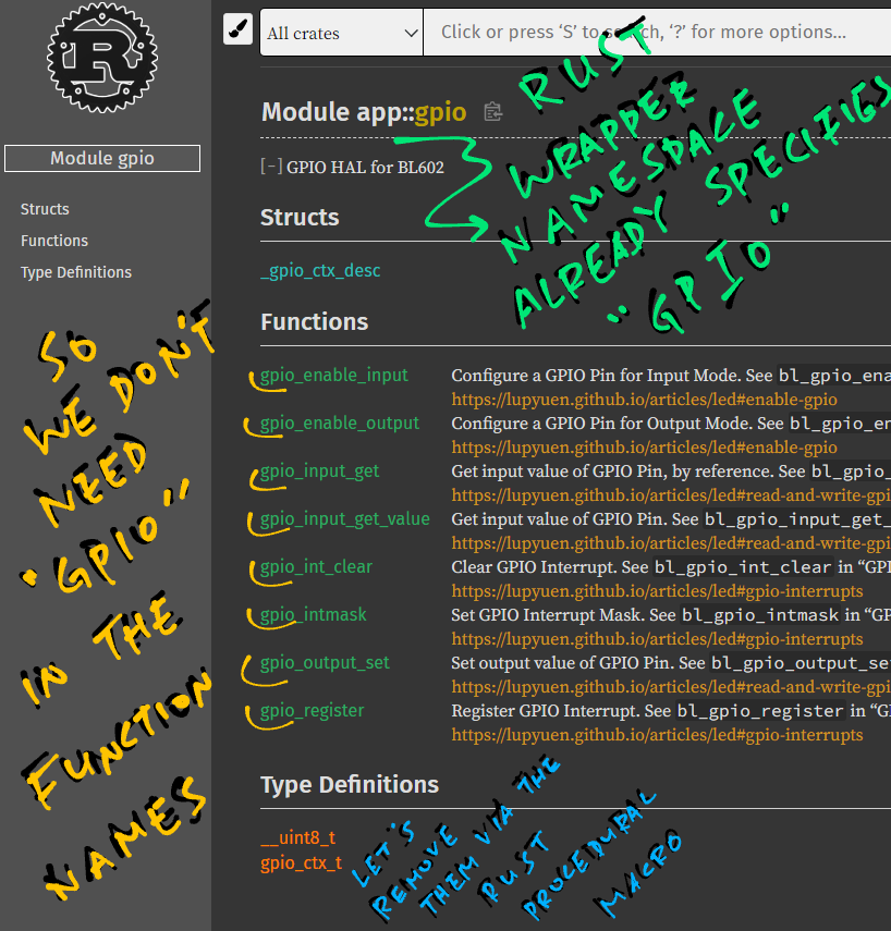
How did we create the docs for BL602 Rust Wrapper? (Pic above)
Sadly BL602 IoT SDK doesn't have much documentation... But much of the SDK is already documented in "The RISC-V BL602 Book"!
So we linked each Rust Wrapper Function to the relevant section in "The RISC-V BL602 Book".
We do this through the Rust doc Attribute...
//  Expanded version of `safe_wrap` macros for the GPIO Rust Bindings
#[doc = "Configure a GPIO Pin for Output Mode. See `bl_gpio_enable_output` in \"Enable GPIO\" <https://lupyuen.github.io/articles/led#enable-gpio>"]
pub fn enable_output(pin: u8, pullup: u8, pulldown: u8) { ...

#[doc = "Set output value of GPIO Pin. See `bl_gpio_output_set` in \"Read and Write GPIO\" <https://lupyuen.github.io/articles/led#read-and-write-gpio>"]
pub fn output_set(pin: u8, value: u8) -> BlResult<()> { ...
How did we inject the doc links into the doc Attribute?
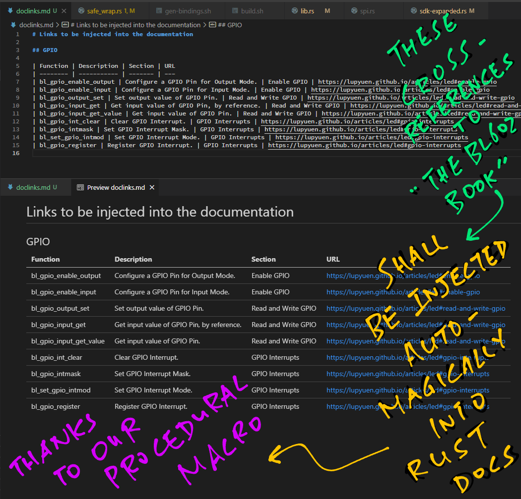
For each Rust Wrapper Function, the links to "The RISC-V BL602 Book" are defined in this Markdown Text File...
| Function              | Description                           | Section             | URL
| --------------------- | ------------------------------------- | ------------------- | ---
| bl_gpio_enable_output | Configure a GPIO Pin for Output Mode. | Enable GPIO         | https://lupyuen.github.io/articles/led#enable-gpio
| bl_gpio_output_set    | Set the output value of a GPIO Pin.   | Read and Write GPIO | https://lupyuen.github.io/articles/led#read-and-write-gpio
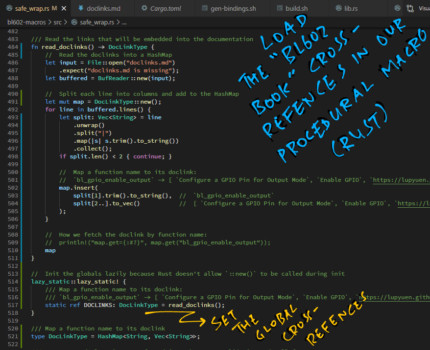
When our Rust Firmware is compiled, the safe_wrap macro loads the Markdown File into memory...
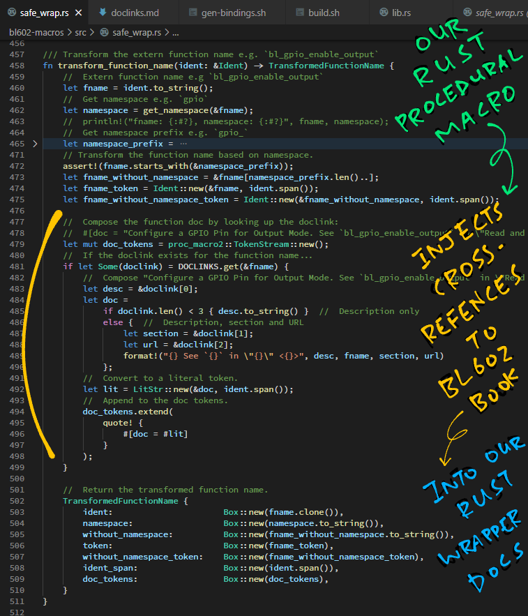
And injects the doc links into the doc attribute...
And the links to "The RISC-V BL602 Book" will magically appear in the Rust Docs!
The safe_wrap macro also shortens the names of the Rust Wrapper Functions.
Here's the original function from the BL602 IoT SDK...
bl_gpio_enable_output
And here's the Rust Wrapper function shortened by safe_wrap...
gpio::enable_output
transform_function_name contains the code that renames the functions: safe_wrap.rs
Testing the improvised Light Sensor on PineCone BL602
