CNC Knowledge sharing thread #126
Comments
|
Hi Guru, Harald |
|
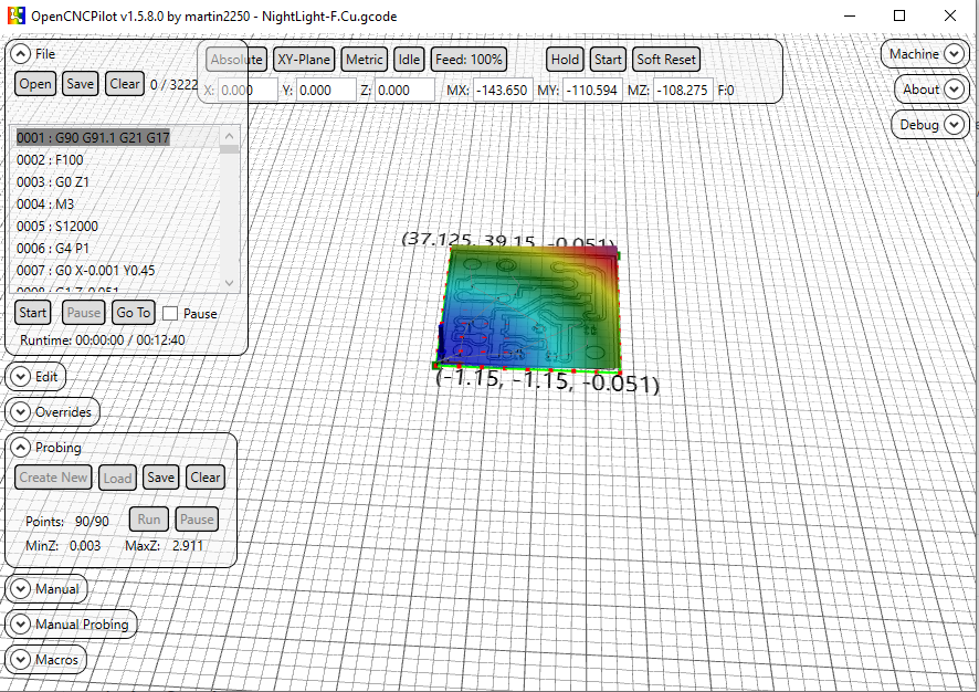
Thanks for the reply Harald. It never probed even a single point. As soon as open probe window, select the area to be probed, the attached screen is what I can see. I can't press the Run button. So no probing of even one point. My CNC stays at 0,0,0 x,y,z respectively. I am missing something. |
|
What happens if you click "Clear" in Probing panel? |
|
When clear is clicked, probing area with that 3d effect goes off as expected. When I create new, probing points appears but again the same issue. Run button will be disabled. |
|
Make sure you don’t have the “generate test pattern” box checked and make sure you click on “size from Gcode” once.
…-TomH-
On Mar 25, 2020, at 1:08 PM, gururajkashikar ***@***.***> wrote:
When clear is clicked, probing area with that 3d effect goes off as expected. When I create new, probing points appears but again the same issue. Run button will be disabled.
—
You are receiving this because you are subscribed to this thread.
Reply to this email directly, view it on GitHub, or unsubscribe.
|
|
Where is the "generate test pattern" box? I tried size from gcode. But did not work. Will try this again tomorrow morning. Thanks for the suggestion |
|
On Probing menu
click “clear”
Click “Create New”
Pops up “New Heightmap” window
Make sure “Generate Test pattern” box Is NOT selected
Click on “Size from gcode” button
Click on Ok
“Run” In probing window should be available to click then.
…-TomH-
On Mar 25, 2020, at 1:34 PM, gururajkashikar ***@***.***> wrote:
Where is the "generate test pattern" box? I tried size from gcode. But did not work. Will try this again tomorrow morning. Thanks for the suggestion
—
You are receiving this because you commented.
Reply to this email directly, view it on GitHub, or unsubscribe.
|
|
Hi tarmon01, You were right. "Generate Test pattern" was checked because of which "Run" button was not enabled. Looks like engraving bit was slightly broken and went bit deeper. I'll try with a new bit. Also I had set the milling depth as 0.6mm in my Gcode. Looks like that can be reduced too. Also one thing I observed. My's CNC Z was not raising up quite high when it is not suppose to mill. Because of this engraving bit went over some of the circuit track and isolated it. Will need to work on this. Any suggestion on the depth of milling and height of the end mill will be helpful. Thanks for all the help. Regards, |

|
Hi Guru! If you use the same bit for probing and for milling (without changing anything at the bit inbetween probing and milling), you don't have to zero Z before probing. But I take it as good practice to zero Z before starting the probing process. Concerning the depth, I use 0.08 mm (80µm) to go through the 35µ copper cladding. Concerning the trenches you milled I propose, you should parametrize some more routes to widen the trenches. Hope that helps... |
|
Hi Harald, Thanks for your time to update these findings. I am using same bit for probing and milling. I was afraid of breaking the V shaped bit if I don't zero Z. Some time when there are error, we hit soft reset and then press Zero machine, I have got couple of V bits broken due to crashing of my machine. Now I think 0.08mm as you said Harald, would be sufficient to engrave the copper clad.. Do we need to do the probing and applying hight map to your drill gcode also? Current PCB looks as attached below. Not very accurate though. But good to go as of now. BTW, the actual issue I mentioned here, was not an issue. It was lack of my knowledge about this tool. So all other things are general discussion. Please suggest me if its ok to discuss these general thing here or should I close this issue? |

|
Hi Guru, Concerning your findings about the wrong step/mm on Z, I suggest you should check those parameters for all three axes. You can adjust this in the GRBL settings. Harald |
|
Hey Harald, I normally use a thick double sided tape to stick the copper clad sheet to my waste wood board and then place the wood on my CNC bed. There will be a gap of around 1 to 2 mm between copper clad and the wood board itself. Hence my drill bit goes all the way down but does not touch the waste wood board. I had found X and Y's steps/mm value and it was accurate. Only Z was missing. Now all three are perfect. One more update :( I lost a 0.7mm router bit today morning when I was trying to cut the board to required size using my CNC. This was because after milling, I could not do the probing.
Any other suggestion for milling, drilling and cutting would be appreciated. Thanks and Regards, |
|
Hi Guru,
I formerly used that thick tape, too, but found, that using thinner double sided tape results in drastically better results.
The thicker version is named "Spiegel-Klebeband" over here in Germany, the thinner version is called "Teppich-Klebeband".
The reason seems tob e, that when probing, the bit stops exactly when it touches the surface.
When milling, it implies some force to the board and this thicker tape lets the board give way.
Not sure whether I got you right, but you surely have to probe only once. You can apply this one time probing to all three files, one after the other.
Harald
|
|
This is the correct one Harald |
|
A tip.
If you “save” the heightmap file you can “load”
It if something goes wrong ( closing opencncpilot by mistake for instance) and then you can apply it to drill/mills on a partially done board when the program is running again. There is also a setting box in the config menu that saves the heightmap file automatically.
…-TomH-
On Mar 27, 2020, at 7:39 AM, deHarro ***@***.***> wrote:
This is the correct one
This is the wrong version
Harald
—
You are receiving this because you commented.
Reply to this email directly, view it on GitHub, or unsubscribe.
|
|
Great tips here. tarmon01 : Very nice to know these option exists. I'll give it a shot tomorrow. Thanks for all this suggestion. |
|
Hi Guru,
In this case you must carefully zero Z (and obviously X and Y as well ;) again, preferably at the same location as you did it first. Harald |
|
Hi Guru,
Since OCP has no option to avoid probing at already etched places, the possibility to just aim at such areas when probing an already treated board is very likely. Harald |
|
Yeah Got it Harald. BTW do you use a different Bit for Engraving and Cutting the board? I saw a video where V shaped bit itself was used to mill and cut the copper clad sheet. I tried with router bit and broke it. The router went deep and stuck there while CNC moved ahead to break the bit.. |
|
Hi Guru, For milling the board outline I use 1,4 mm (sometimes 1,0 mm) "diamond toothed" or "spiral-toothed" drill bits. Harald |
|
Hi Harald and tarmon01, After applying height map, when I engraved the board, I saw that the bit went deeper towards the left of the board, but just touched the board on the right side. My question to you : Is it need that we need to get probing some how from bottom to top as shown in the video of this website (instead of bottom left to right) to get correct probing height. For earlier board, probing was done from bottom to top as in the video. So I have this doubt.
Image attached in case you want to see it. Tracks are too thick... Gururaj |


|
Gururaj,
I don’t think it matters where it starts. Martin would know for sure.
I did once do a heightmap, realized I forgot something that grew the board size and did not do a new heightmap, because I already did one, 🧐and the traces looked great until it suddenly they stopped etching correctly when they hit the edge of the heightmap. A learning experience.
I always start my projects in the center of the board. I also go quite a bit deeper with my bit 0.19mm. This for me always seems to work. But I use a 60 degree carbide etching bit. And I am mostly doing 30mil traces which isn’t very fine.
https://www.amazon.com/3-175mm-Engraving-EnPoint-Carbide-Aluminum/dp/B019K5G6AI
I gave up on the really really cheap 30 degree-ish bits as the very tip always seemed to break even if I slowed down the mill down to deathly slow speed.
But the other folks here have had better luck with those bits and could advise better.
Thanks,
…-TomH-
On Mar 28, 2020, at 12:11 PM, gururajkashikar ***@***.***> wrote:
Hi Harald and tarmon01,
I create another PCB today. Had a different experience. I used 0.08 as the depth for PCB milling/Etching. My probing started from Bottom Left of the board, went horizontally i.e. left to right, then 5mm up right to left so on till it reached Top Right. (Attaching the image to make this clear)
After applying height map, when I engraved the board, I saw that the bit went deeper towards the left of the board, but just touched the board on the right side.
My question to you : Is it need that we need to get probing some how from bottom to top as shown in the video of this website (instead of bottom left to right) to get correct probing height. For earlier board, probing was done from bottom to top as in the video. So I have this doubt.
Though I used 0.08mm as the depth, looks like it went deeper on left side of the board. Is this problem due to above question.
Gururaj
—
You are receiving this because you commented.
Reply to this email directly, view it on GitHub, or unsubscribe.
|
|
Thanks for the update torman01. I think I need to buy 60 deg bits like you have suggested. What do you use for cutting board to its correct measurement.? Can you please share some pics of boards and your CNC machine. |
|
My name is Tom😃.
I have designed & built my “Mini-chine “ to use 4 tools without changing bits; A pcb carver bit, A .9mm drill, cutout tool( 2mm but I may change it to 1mm), and a pen plotter. It’s based on several parts of the standard Chinese kits but I’ve had to make several aluminum pieces on my big CNC “Chine” machine. I use a decent spindle for the traces and 2 cheap spindles for drilling/cutout as those 2 functions don’t require the same precision.
Martin has modified openCNCpilot such that it will allow me to pass addition gcodes through so I can make a whole board in one gcode file( but I haven’t tested his changes yet). I do not use double sided tape but I do have a backing board that makes contact to the circuit board with clipboard clamps. I use .19mm for traces and 1.9mm depth for cutting/drilling.
It is not perfect yet.. the x axis has too much backlash that I need to fix. But it is good enough for the moment until I can get around to fixing it. I am also in the process of designing a single Arduino shield instead of the several little boards shown in the pictures above, that work with the controller that came with the kits.
Some things that may help you. These are meant as a helpful comments. Your machine has too much backlash in it, going by the picture you sent. Circles should circles not ovals. Also the alignment of drills to the etching are not centered.
Anti- backlash nuts would help assuming you don’t have them on ? If you do have them on, make sure the spring is fully compressed and not loose when you screw them on. Also use precise right angles to ensure that X,Y,and Z are perpendicular although X & Y are less important for you than me as you use doubled sided tape to hold the board on and that is likely not going to be very square. Make sure whatever structure you are using is as stiff/rigid as you can make it. if it wobbles or deforms. That’s not good.. add supports as needed so it does’t move when you push on the moving parts by hand. ( or at least minimize it)
Hopes this helps!
FYI. If you are interested in other things I do, my website is TnRCrafts.com.
Thanks,
…-TomH-
On Mar 28, 2020, at 3:13 PM, gururajkashikar ***@***.***> wrote:
Thanks for the update torman01. I think I need to buy 60 deg bits like you have suggested. What do you use for cutting board to its correct measurement.? Can you please share some pics of boards and your CNC machine.
Btw can I know your real name.
—
You are receiving this because you commented.
Reply to this email directly, view it on GitHub, or unsubscribe.
|
|


|
Missing, but alas sideways,🙃 photos for last post -TomH- |
|
Hi Tom, The PCB quality is also excellent. Regarding my CNC machine, it's home made machine with V slot aluminium profile, v wheels and movement is through timing belt. See the image below. Regarding electronics, I have arduino nano on grbl CNC shield v4. One single board with stepper controller on it. Lot of work to do before I get PCB like yours. Thanks for you inputs. It matters a lot at this time Regards, |

|
Hi everybody, just to chime in and answer a few of the questions: OpenCNCPilot always chooses the closest point to the current position for probing. This means that the probing pattern can be different from time to time. Assuming your machine doesn't loose steps, different probing orders don't make a difference. If the milling depth varies from side to side, it's always an issue with rigidity, either in the machine or the board. I only recommend tape (over the entire board surface, not just small pieces) to hold down boards, and I'm actually quite surprised that Tom's boards come out that cleanly with just two clamps. Regarding backlash in your machine: timing belts can be quite good in that regard. My first machine, a Shapeoko 2, also used V-rails and timing belts. The best I could do were 0.4mm traces and 0.8mm pitch SMD components. There are a few catches though:
@tarmon01 impressive setup! How do you manage the multiple Z axes with grbl? Martin |
|
Guru,
Pretty cool to create what you did! I like the innovation you used on the slides.
The belts work best for a laser engraver which has little resisting force when it moves in x and y directions. A spindle requires a very rigid structure as you don’t want the spindle to tilt in opposition to the direction it is going. Pretty sure that explains the results you are getting.
So if you can get lead screws for x and y, that’s probably the best way to go. If you can’t then using some pulleys and steel wire to Implement something called a “moving knot” in x and y can help to prevent “racking” which is what it is called it when the structure goes out of square ( which it does when carving)
Here is a great site for help and to see others peoples design if you have seen it already
tps://www.cnczone.com/forums/diy-cnc-router-table-machines/
Here’s some info on the “moving knot”
https://m.youtube.com/watch?v=V_RsIIGw0xk
https://www.cnczone.com/forums/diy-cnc-router-table-machines/51485-make-gantry-rock-solid.html
Thanks,
…-TomH-
On Mar 28, 2020, at 9:58 PM, gururajkashikar ***@***.***> wrote:
Hi Tom,
Thank you so much. Your machine is impressive. I never thought we can have multiple spindle on a single machine. Looks awesome.
The PCB quality is also excellent.
Regarding my CNC machine, it's home made machine with V slot aluminium profile, v wheels and movement is through timing belt. See the image below.
I'll surely work on your comment. Since I don't have threaded road and nut for X and Y axis, I need to check how to avoid Anti-backlash. The CNC as whole doesn't shake or wobbles. But moves easily by hand. I need to work on that as well.
Regarding electronics, I have arduino nano on grbl CNC shield v4. One single board with stepper controller on it. Lot of work to do before I get PCB like yours. Thanks for you inputs. It matters a lot at this time
Regards,
Guru
—
You are receiving this because you commented.
Reply to this email directly, view it on GitHub, or unsubscribe.
|
|
Martin,
There are 4 hold downs. Two clipboard clamps, and two thumbscrews that hold aluminum pieces that overlap the board edges. I One clipboard provides electrical contact for the board probing.
The clipboards are spaced apart for the inexpensive copper clad boards to slide between on Amazon.( a little over 100mm I think).
What Grbl doesn’t know about, It can’t complain about< heh>.
Grbl however does support 2 coolant controls as well as work offsets. Which is enough to drive 4 different tools with the proper circuitry and Gcode mods.
If you used belts perhaps Guru can also, I’ll leave that in your capable hands.
Thanks,
…-TomH-
On Mar 29, 2020, at 5:20 AM, Martin Pittermann ***@***.***> wrote:
Hi everybody,
just to chime in and answer a few of the questions:
OpenCNCPilot always chooses the closest point to the current position for probing. This means that the probing pattern can be different from time to time. Assuming your machine doesn't loose steps, different probing orders don't make a difference. If the milling depth varies from side to side, it's always an issue with rigidity, either in the machine or the board. I only recommend tape (over the entire board surface, not just small pieces) to hold down boards, and I'm actually quite surprised that Tom's boards come out that cleanly with just two clamps.
Regarding backlash in your machine: timing belts can be quite good in that regard. My first machine, a Shapeoko 2, also used V-rails and timing belts. The best I could do were 0.4mm traces and 0.8mm pitch SMD components. There are a few catches though:
The rolling resistance of your bearings must be very low. Try disconnecting the motors and adjusting the rollers until XY moves with little to no resistance.
The belts mustn't be too cold. My boards turned out worse in winter, even with the machine sitting in my bedroom.
Belts tend to 'remember' their shape, so after sitting around for a while, there will be a 'bump' when moving over the resting place. My solution was to un-tension the belts when the machine was not in use.
The belts must be tensioned properly of course.
@tarmon01 impressive setup! How do you manage the multiple Z axes with grbl?
Martin
—
You are receiving this because you were mentioned.
Reply to this email directly, view it on GitHub, or unsubscribe.
|
|
Hi All, So as most of you suggested here, I modified my CNC to have X axis fixed. See the image below. Just did first ran of this new machine. Following is the image of my experiment. With this I have only one steeper in Y axis. So one stepper and one lead screw saved with this design. Also as said less load on Y axis stepper as it's not carrying Y and Z axis with it. Regards, |


|
Hi Guru, I think, you will get much improved results, if you fasten the X stepper with some additional screws. Let's say a total of 4 will do very well, 2 will make it better, too. This one thin screw, you have at the moment, is not stiff enough, to hold the stepper steady against it's torque when moving the sled. Harald |
|
Hi Harald, Thanks for your reply. I'll change the screw for the stepper motor. Currently that stepper has 2 screws diagonally opposite to the one visible in the picture above. Isn't it Y axis stepper which we are talking about here? As you said this stepper can be slightly moved up and down. So I'll have a higher dia screws and possibly 4 of them... Thanks again. Regards |
|
Hi Guru, I didn't mean up and down but turning it sideways, as the momentum of it's own power would do when stepping to turn the lead screw. I think, up and down would not imply errors in the lead screws direction, but turning momentum will. Your idea, using thicker screws and 4 of them will improve the stability noticeable, I believe. Harald |
Woooh!!!!! This is a complete make over! Congratulations Guru, well done. You could also stabilise stepper motor by sandwich a second plywood between it and CNC frame.
Hanspeter. |

|
Hi Harald, Hanspeter, I added a thicker Nuts and Bolts for the Stepper motor and got it very stable now. Image attached below.
The whole CNC machine looks like the image below. Less number of floating/moving wires..
I did couple of dry run and here are results.
BTW, I also modified the Z axis, as it was Tilted. The Acrylic sheet, I used earlier used for mounting Spindle motor on Z axis was bent due to V-Shaped wheel pulling it in. So added a wood instead. Now no more tilt on Spindle. Thanks for all the support you people are providing... -Regards, |


|
Hi Guru, looks pretty good now :) So, on to your next PCB ;-) Harald |
|
Guru,
Excellent! Your improvements to the machine and the corresponding output looks very good.
-TomH-
|
|
Thank-you Tom and Harald. I'll try PCB milling soon |
|
Hi Martin,
Bottom is not straight because the machine to start at previously pointed zero. This is the reason I wanted to know X, Y on mouse over. Thanks and Regards, |

|
Cool! Looks great (even if I cannot read it). I have the same problem sometimes. Harald |
Thanks for the reply Harald. Hope you are doing good. Regards. Gcode file, |
|
Hi Guru!
Yes, that would be the first idea. Concerning probing non conductive materials I have made different approaches. Please have a look at my homepage: The first two URLs describe the modification of two more or less identical 3DTouch sensor clones resembling version V1 of BLTouch to cooperate with GRBL. This is not funny to accomplish, so I made a different approach, to make reproduction easier. Those sensors imply near to nothing in forces onto the to be probed material. At the moment I am disappointed by the results from this third version, I already elaborated on that over there and the next 3..4 postings there. I will modify one of my pimped 3DTouch sensors to produce positive touch signals and attach it to the interface to get comparative readings, just to be able to judge, whether the new 3DTouch V2 is the culprit or my interface. Harald |
|
Hi Guru, Hi Harald, so if I understand correctly, your problem is that you loose the origin when you have to do an emergency stop? There is a simple solution for that if you have end stops. Just use G10 to set the origin. That way, work coordinate systems are stored in EEPROM and will be restored after homing the machine. Cheers, |
|
Hi Martin, Also to get to correct origin, after missing steps due to unknown reason like stuck end mill, we need to home the machine and then use G10/G28. Instead what me and Harald where thinking is if we can know the X and Y on the path, we can move to that location using manual jogging, then use G92 X..Y.. to set X and Y. After this when we hit G01X0Y0FXXXX, it moves to correct Origin and we can start immediately. Only know X and Y to us is the first one from the Gcode file. One more need to know the exact X and Y position from Gcode file is as follows Assume that we have executed 3500 lines of Gcode (CNCPilot at this point might have streamed 4000 lines of gcode and will be showing the same on the screen) and then we see some issue. Immediately I would have pressed Y hardlimit to stop the machine (Note: I am not pressing Emergency s/w as it restarts the Arduino). Instead of starting all over again, what we can do is if we get to know X and Y of the current position, clear hard limit alarm, set that value fro X and Y using G92 and start from 3500th line rather than starting from the beginning. There are may cases like this where we can set the current X and Y and start from there if we can know about it. Thanks and Regards, |
|
Hi Harald,
Thanks for the link. I went through it. I assume you have ATTiny chip to probe the metallic surface like PCB. I'll read about it tomorrow throughly as Google is helping me to translate the page to English. Is my idea to probe material's height using some kind of Ultrasonic sensor, LDR, capacitance touch sensor, Proximity sensor etc feasible? Please let me know your thought. Thanks & Regards, |
|
Hi Guru, metallic surfaces I probe with the V-Bit. In this case no AtTiny is needed. Please read about BLTouch probes at Antclabs. They provide info about the different possibilities you mention to probe non metallic surfaces and their drawbacks in comparison to the BLTouch. The BLTouch or 3DTouch (the latter are clones of the original BLTouch) use a very light stick of aluminium or plastic for sensing the touch down on the material. The interface with AtTiny85 I present on my homepage is solely to make the use of such (unaltered) BLTouch sensors possible in combination with GRBL.
Harald |
|
Hi All, https://www.youtube.com/watch?v=YNwaRFlIYsw Thanks and regards, |
|
Hi Guru, Harald |
|
Hello Guru, Wishing all the best. Hanspeter. |
|
Hi Harald, Hanspeter, Thanks for your comments. Yes I tried to mill a PCB Yesterday.Result was not bad. Watch this Video. Also if you are interested in my 3D printer here is the video of it. Thanks for all the support, Suggestion provided to me through this channel. Regards, |
|
Hi All, Good morning. Just wanted to share few pics of milling PCB in my new CNC. Once again Matrin, big thanks to your OpenCNCPilot software. Harald, Hanspeter cant go without thanking both of you for awesome support given by you. Thanks to all in this group without your support this would have not been possible. |

|
Hi Guru! [edit]
This leads to the following carvings.
I have no photo on hands, but if you like and need, I can make one later in the day. |


|
Hi Harald, Thanks for the suggestion about the grid size. To reduce time of auto-probing, I had increased it to 10 or may be 14. I was scratching my head why some of the places its not going deep enough to mill the copper. I'll use 5 as grid size and go a PCB milling. W.r.t Text, I used to have Vector fonts in Eagle software. But in KiCAD I was not able to find one. So used normal font. Will do some more searches on how to get the Vector fonts in KiCAD. Overall great suggestions. Thanks. I had another query. Suppose I switched off the machine after milling is done. I have not used G54 to 59 to save the co-ordinates. How do I get back to zero position to start the drilling process? -Guru |
|
Hi Guru, You are right, I use Eagle, so vector fonts are on hands. I do not use coordinate saving via G54..59, since I do not understand the underlying scheme. In general I mill the traces, the text and the drills without moving the board at all. ... ok, reading your question again, I realize "switched off" 😄 I have end stops installed, but do not use them since I had issues with EMI. Sporadically the end stops were triggered from disturbances in the air, so I disabled them. Harald |
|
Yeah, I know we should do milling drilling and board cutting at the same time. But my spindle was over heated and wanted to give it some time (May be 30 to 40 minutes) for it to cool down. So I turned the whole machine off. After spindle was cooled, when I turn on the machine, though the spindle was in Zeroth point, my machine co-ordinates will be MX=0, MY=0 and MZ=0. So it forces me to home it first and then go to Zero position of my workpiece manually. I found one way. But not very accurate though. I'll jog to first drill point manually by seeing the picture on OCP and trace on copper clad board. I'll lower the spindle with drill bit (Still not spinning) bit to see if the hole will be drilled in the center of the copper as required. If everything goes fine, I'll use G92 to set the X and Y. For ex: If the first point in Drill Gcode file is G00 X35.4000 Y57.1300, after moving to correct location I use G92 X35.4 Y57.13. After this, when I issue command G01 X0 Y0 F500, It comes back to original 0 Position. BTW, I use hardware limit switch without any issues. I have wired it as COM - NC -> GND with 10K pullup resistor. Which means the Switch is normally connected to ground. When triggered, It just get disconnected from GND and 10K will pull that line high for fraction of second which will be treated as limit s/w triggered. No EMI issue at all as most of the time the X,Y,Z limit switch lines are grounded. Hope this helps. -Guru |
|
Zeroing after power loss: The described procedure (find an already drilled or - not so good - a to be drilled hole) works well enough for me. I used that often in the past. Limit switches: Yes of course. My switches are NO and pull the signal to GND when triggered. Harald |
|
Hi all!
The design is as follows:
Beneath the alu block sits a steel plate, both are connected via M8 scews. All together it will work as adapter for our hydraulic jack to lift the car for changing the wheels. Harald |


|
Hi Herald, Regards, |
|
Hi Guru, First I used a 3 mm bit with one tooth. This leads to 22000 rpm and 550 mm/min cutting speed... resulting in over 2 hours of cutting.
Concerning the quality of the surfaces I am not totally satisfied:
But the part will do its job :) The trench is cut in two runs, each 10 mm deep. This results in a step at 10 mm. I removed it with a file. The 3 mm bit is a little bit cluttered with alu afterwards, but didn't brake (left: used, right: new):
Concerning the cutting parameters, I adapted a PDF from Sorotec and made an Excel table to easily calculate the parameters for different materials: It helps in getting started when milling different materials for the first time. Harald |


Hi Martin,
First of all, thank you for this wonderful software.
I was able install Grbl 1.1J and use OpenCNCPilot to move all 3 axis using manual mode as well as using Keyboard. Just wanted to make sure that I have met pre-requisites (grbl 1.1 and .NetFrameWork 5).
I was also able to utilize "Probe and set Zero" macro to check if my probing is functioning properly. It is working as expected.
I was trying to use the most awesome part of this software, Probing. But "Run" button is not getting enables. What I am missing here? Could you please throw some light on this. Attaching image of my Screen for your reference.
Thanks in Advance.
Regards,
Guru
The text was updated successfully, but these errors were encountered: