PCB cad as a png #61
Comments
|
I'm not sure what you are after here? |
|
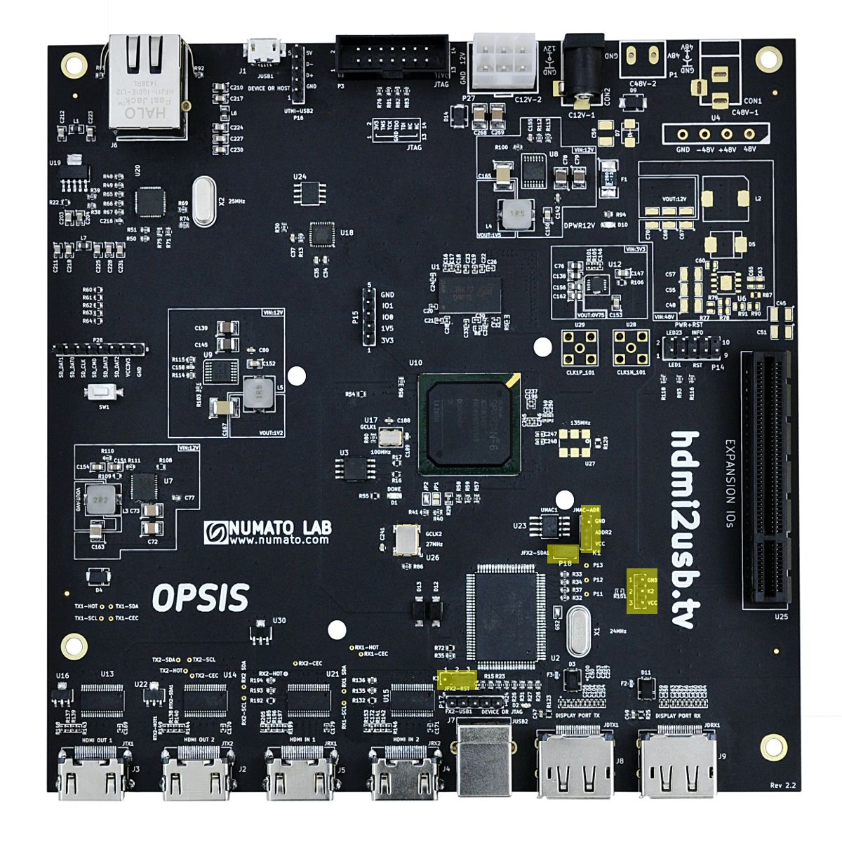
in this image, some of the text is hard to read: I am assuming there are cad files and software that can render crisp lines and more detail. |
|
If I may help, I agree that having the render of the board easily accessible is useful. It may be a PDF top in one page and bottom in another (copper and silk layers). A way I found to avoid committing generated files (akin to compile artifacts) to the repo while also having files to aid production and references was to use the release. An example may be seen here: https://github.com/lnls-dig/rffe-uc-hw/releases The first zip file are the Gerbers, ODB, etc. The PDFs are outside this zip for easier reference. As they are associated with a specific batch, it also serves as a permanent reference for this specific version of the board. No need to download the source, the right version of the tooling and regenerate everything, and no risk of having the repo out-of-sync. In Kicad it should be easy to automate this release process by scripting.
|
render the PCB cad file as a png to add to the photos of the board.
mostly I want to see part placement and labels. Like I want to zoom in on the labels around the reset header.
I'll admit this seems like committing compiler artifacts, which need to be kept in sync, but given this is manufactured hardware in production it is different.
The text was updated successfully, but these errors were encountered: