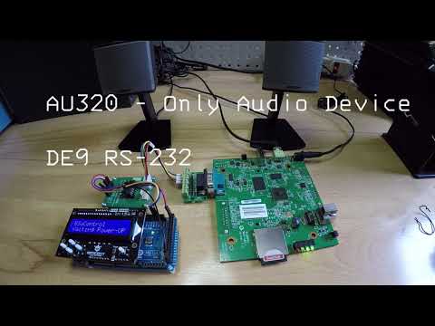
This script is designed to control BrightSign units efficiently using any controller with a serial interface, included arduino.

The following list shows the models that have been tested with this script, but it will surely work on another model in the same series as well.
| Model | Serial Port Type | Hardware Level | Firmware |
|---|---|---|---|
| AU320 | Onboard DE-09 | RS-232 | 6.1.76 |
| LS422 | USB to Serial Adapter | TTL/RS-232 | 6.2.147.9 |
| LS423 | USB C Serial Built-in | TTL | 8.5.47 |
| LS424 | USB C Serial Built-in | TTL | 8.5.47 |
| HD223 | GPIO connector AF | TTL | 8.5.47 |
| HD224 | GPIO connector AF | TTL | 8.5.47 |
| HD1023 | Onboard 3.5mm Serial | TTL | 8.5.47 |
| HD1033 | Onboard 3.5mm Serial | TTL | 8.5.47 |
| HD1024 | Onboard 3.5mm Serial | RS-232 | 8.5.47 |
| HD1034 | Onboard 3.5mm Serial | RS-232 | 8.5.47 |
| XD233 | GPIO connector AF | TTL | 8.5.47 |
| XT243 | GPIO connector AF | TTL | 8.5.47 |
| XT1143 | Onboard 3.5mm Serial | TTL | 8.5.47 |
| HD1025 | Onboard 3.5mm Serial | RS-232(Tx and Rx)/TTL(Rx) | 9.0.145.1 |
AF: Alternate Function
Please check the technical specifications of the serial port, in particular the tolerated voltages.
Simply add this script and your content to the flash card and you can send the list of commands below to control playback.
The commands are case sensitive. The unit automatically responds when a command is received.
| command (chars) | argument type | response STATUS (hex) |
|---|---|---|
| PLAY | File Path | 0 : error 1 : ok |
| STOP | none | 0 : error 1 : ok |
| DISPLAY | File Path | 0 : error 1 : ok |
| VOLUME | INT (%) | 0 : error 1 : ok |
| PAUSE | none | 0 : error 1 : ok |
| RESUME | none | 0 : error 1 : ok |
| LOOP | String | 0 : error 1 : ok |
| REBOOT | none | none |
Command Syntax: <command><argument><cr>
The path and filename is used in uppercase as this is how brightsign handles files internally.
| command example | description |
|---|---|
PLAY VIDEO.MOV |
Play video file called "video.mov" in root directory |
PLAY AUDIO/AUDIO.M4A |
Play audio file called "audio.m4a" in "audio" directory |
DISPLAY IMG/TEST.PNG |
Uses the video decoder to display image file called "test.png" in "img" directory |
VOLUME 50 |
Set the volume to 50 percent of normal |
STOP |
Stop the currently playing media and clears the screen |
LOOP AlwaysLoop |
Enable automatic loop mode |
The below table Specifies the looping modes for media playback. Media End events are only sent if seamless looping is disabled, or if the mode is set to "SeamlessLoopOrNotAtAll" and the file cannot be looped seamlessly.
| LOOP argument | description |
|---|---|
| NoLoop | Looping is disabled in all cases. This is the default behavior, allowing for playback of multiple files in a playlist—with noticeable gaps between the end and beginning of the file. |
| AlwaysLoop | The video is looped seamlessly if possible; otherwise, it is looped with seams. |
| SeamlessLoopOrNotAtAll | The video is looped seamlessly if possible; otherwise, it is not looped at all. |
| LoopButNotSeamless | The video is looped with seams. |
NOTES:
- When media file is a video, the PLAY command stops on the last frame.
- cr is carriage return
The response start with STX (02h) followed by the status byte and lastly an ETX (03h).
<STX><STATUS><ETX>
When the unit starts up and has the script installed, the status online (02h) is sent.
02h 02h 03h
Unit responds automatically with media_ended (08h) when a file has finished playing:
02h 08h 03h
When the last command was not executed correctly, the unit responds:
02h 00h 03h
When the last command was successful, the unit responds:
02h 01h 03h
The LS423 and LS424 units has a USB 2.0 Type-C port, this port is configured in alternate mode using pins A2/A3 and B2/B3 as a TTL serial port.
The following table illustrates the pinout of the USB 2.0 Type-C host port:
| pin | Signal Name | Description | pin | Signal Name | Description |
|---|---|---|---|---|---|
| A1 | GND | Ground return | B12 | GND | Ground return |
| A2 | TX1+ | Serial Transmit | B11 | ||
| A3 | TX1- | Serial Receive | B10 | ||
| A4 | VBUS | Bus Power | B9 | VBUS | Bus Power |
| A5 | CC1 | Configuration Channel | B8 | ||
| A6 | DP1 | Positive Half USB 2.0 Position 1 | B7 | DN2 | Negative Half of USB 2.0 Position 2 |
| A7 | DN1 | Negative Half USB 2.0 Position 1 | B6 | DP2 | Positive Half of USB 2.0 Position 2 |
| A8 | B5 | CC2 | Configuration channel | ||
| A9 | VBUS | Bus Power | B4 | VBUS | Bus Power |
| A10 | B3 | TX2- | Serial Receive | ||
| A11 | B2 | TX2+ | Serial Transmit | ||
| A12 | GND | Ground return | B1 | GND | Ground return |

The serial port is enumerated as port 0.
The USB connector can supply up to 500mA of power for peripherals. The maximum length for a USB cable is 5 meters.
The USB Type-C port will output analog audio if the CC1 and CC2 signal is shorted to ground via a 1K resistor. Analog output can also be enabled in system software. The D+ signal outputs right audio, and the D- signal outpts left audio.
On some BrightSign models that have onboard GPIO connector it is possible to use them with an alternate function, including a TTL serial port. This method is currently supported on the XTx44, XTx43, XDx34, XDx33, HDx24, HDx23, and HO523 models.
The following table outlines the possible alternate setting for each pin:
| GPIO Pin | Native Function | Alternate Function |
|---|---|---|
| 1 | GND | N/A |
| 2 | VDD | N/A |
| 3 | Button 0 | serial1 (Rx) |
| 4 | Button 1 | irin1 |
| 5 | Button 2 | irout (HDx23, HO523 only) |
| 6 | Button 3 | N/A |
| 9 | Button 4 | serial0 (Rx - console port)* |
| 10 | Button 5 | serial0 (Tx)* |
| 11 | Button 6 | serial1 (Tx) |
| 12 | Button 7 | N/A |
GPIO alternate function serial is always TTL.
The GPIO port is a Terminal Block 12 Pin male standard design manufactured by Phoenix Contact.

*Models that do not have a 3.5mm serial port (e.g. HD223, XD233) do not support serial port 0.
The RS-232 interface is a male DE-09 connector. The following table illustrates the pinout.
| Pin | Description | Pin | Description |
|---|---|---|---|
| 1 | NC | 2 | Receive data into the device |
| 3 | Transmit data out of the device | 4 | Available 5V @ 500mA |
| 5 | Ground | 6 | NC |
| 7 | RTS | 8 | CTS |
| 9 | NC |
Here is the DE-09 male as viewed from the front of the BrightSign units.

The UART (asynchronous serial) interface is a 3.5mm (1/8") jack for communication. This serial interface supports TX, RX, and ground only.
The 3.5mm serial port has the following configuration (from the perspective of the player):
| Pin | Function |
|---|---|
| Tip | Receive |
| Ring | Transmit |
| Sleeve | Ground |

There are some models that are compatible with RS-232 voltages, see the following table:
| Series with 3.5mm serial | RS-232 Compatible |
|---|---|
| XT4 | YES |
| XD4 | YES |
| HD4 | YES |
| XD3 (Revision H and newer) | YES |
| XT3 (Revision H and newer) | YES |
| XD3 (Revision G and older) | NO |
| XT3 (Revision G and older) | NO |
| HD3 | NO |
| LS424 | NO |
| LS423 | NO |
The player hardware revision is the third character in the serial number. For example, the serial number "11G738001237" is rev G of that player model.
At the moment on LS422 units, it is only possible to use serial communication using a USB adapter. This script has been tested in conjunction with the following adapters, but it may well work with any other.
| Brand |
|---|
| Silicon Laboratories |
| WinChipHead - CH340 |
| Future Technology Devices International |
| Prolific Technology Inc |
The following are the default serial settings for a BrightSign player. They can be changed in the script.
| Default serial settings |
|---|
| Baud rate: 115200 |
| Data: 8 bit |
| Parity: None |
| Stop: 1 bit |
The following diagram illustrates the behavior of the TX and RX signal:

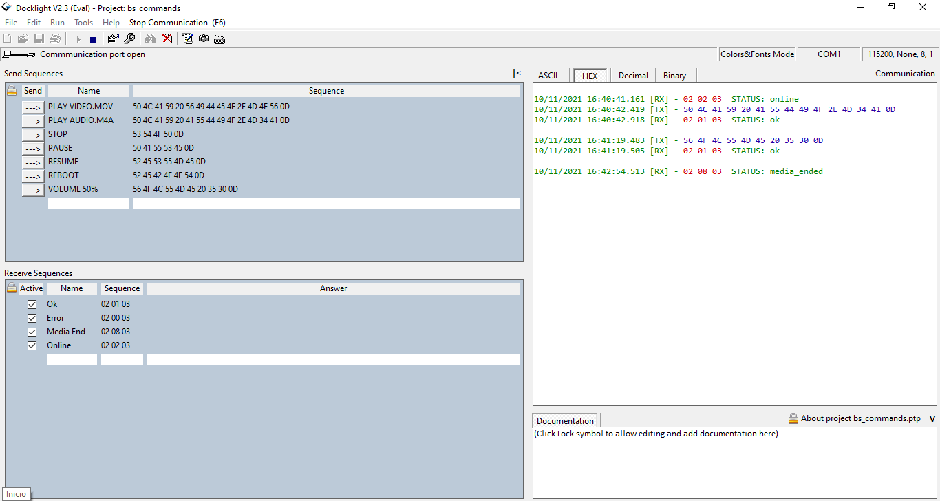
Docklight is a testing, analysis and simulation tool for serial communication protocols.
Use the following project to use BrightSign unit connected to a PC running Windows OS.
BrightSign is a library for Arduino.
LS424 need a power cycle