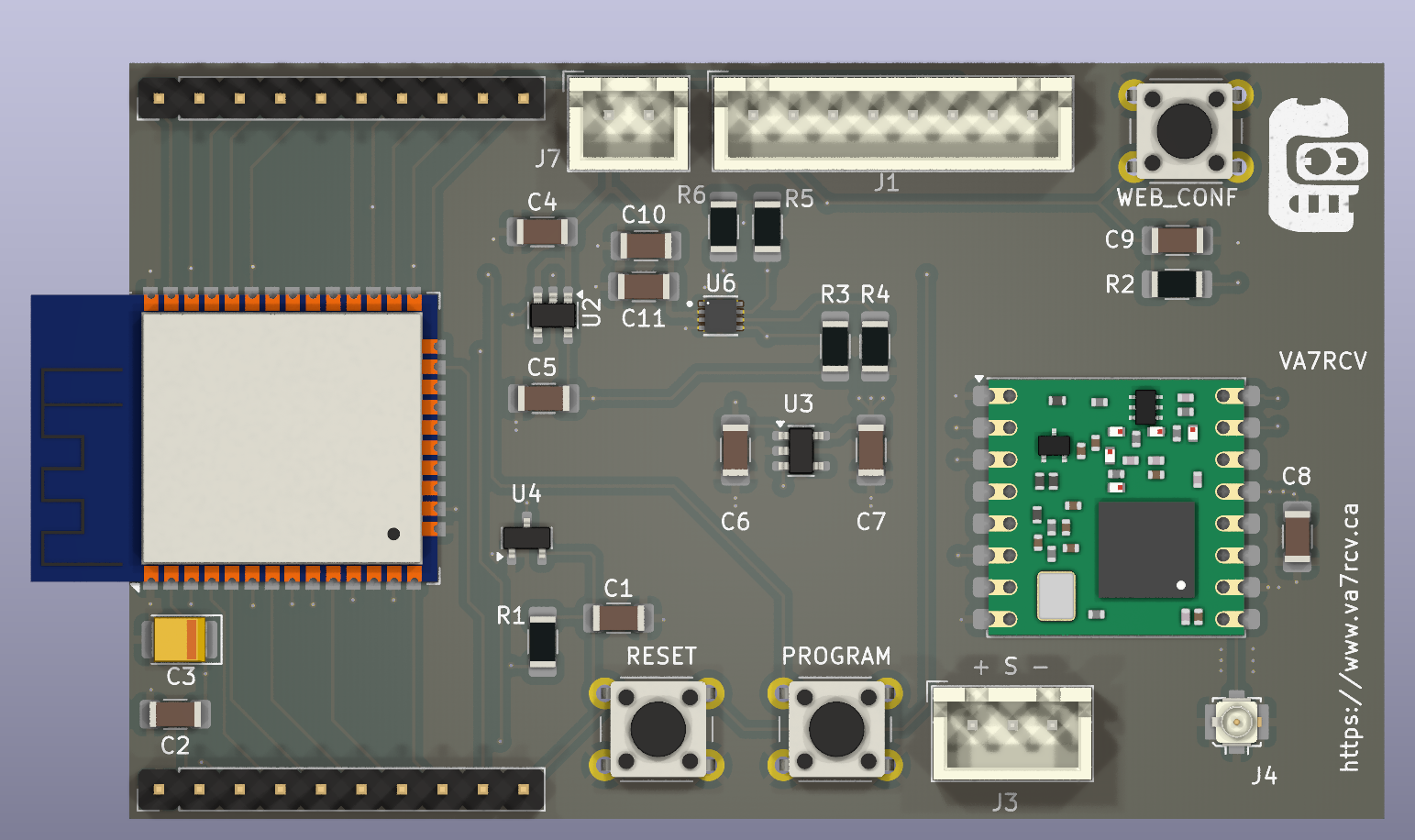
This is a low-power, ESP32-powered LoRa board designed for general purposes. For this project, I used the board with a capacitive soil moisture sensor to monitor my houseplants.
This is a 4-layer PCB board that features a NICERF RFM95W for the LoRa radio and an ESP-WROOM-32D as the microcontroller. Two XC6220B301MR-G LDOs create two separate power rails at 3.0V.
The first power rail supplies power exclusively to the microcontroller (MCU), while the second rail serves as an instrumentation line that becomes active when the ESP32 wakes up from deep sleep. This rail powers both the radio and the sensors. Additionally, the MAX17048 includes a LiPo fuel gauge.
There's a WS2812B LED that provides feedback to the user.
-
Red: The node does not have a valid configuration or is in WebConfig state (AP Mode).
-
Green: Node successfully joined TTN after configuration.
-
Orange: Error Joining the TTN network.
-
Unless the above events happen, the LED remains powered off at all times.
The Lora deep sleep routines are based on Andreas Spiess Lora Mailbox with DeepSleep, but instead of using the EEPROM routines to save the LMIC status, I used the Preferences library
This project uses the ArduinoLMICC library.
This Firmware has a lot of debug code and requires some re-organization it is a PoC and it has been running for about 3 moths without any issue.
-
Add downlink capabilities to trigger WiFi join and do OTA.
-
Investigate how to add crypto validation of the firmware.
-
Re organize the code, WiFi menu and config is a mess.
-
Remove debug code.
-
Standardize LED feedback colors.
Data is sent to the Things Network using CayenneLPP, This project uses the (electroniccats/CayenneLPP)[https://github.com/ElectronicCats/CayenneLPP] implementation, I found this to be the implementation that had extended support for extra data fields.
-
Create an application.
-
Add the Payload Decoder from the (electroniccats/CayenneLPP)[] project.
-
Create an device use: LoRaWAN Specification 1.0.3, RP001 Regional Parameters 1.0.3 revision A
-
Build the firmware and upload it to the board.
-
The board will enter in config mode, and access point named lora-node will be created.
-
Connect to the wifi and open 192.168.4.1 in your web browser, and configure the node paramethers.
3.1 Provisioning Menu:
Once the node is provisioned, and joined your applicaton in The things network.
-
Rested the board and measure the reading in Air-Free / Dry conditions and record raw sensore reading, you can see it in the serial console or in TTN.
-
Submerge the soil sensor in water and reset the board and record the raw sensor reading.
-
Press the WEB_CONF button and reset the board leaving the WEB_CONF button pressed, the board will enter in configuration mode and a WiFi Access point named lora-node will appear, connect to it and go to 192.168.4.1 in your browser.
-
Input the Free-Air and Water values recorded in steps 1 and 2.
Calibration is done.
You need to configure an MQTT bridge between TTN and your Local MQTT server, there's plenty of information on how to do this online.
The Node-Red folder has Auto-Discovery, that you can use as a starting point for MQTT auto discovery.
There's also a Telegram bot that will notify you when the Node has not been seen in 24 Hours.
Under the enclosure directory you will find STL files to print the sensor enclosure, you can 3D print the board holder and it will fit a 2.5 Inches PVC Pipe ( Internal Diameter ).
There's also a 3D model of a pipe you can print for indoors applications.


