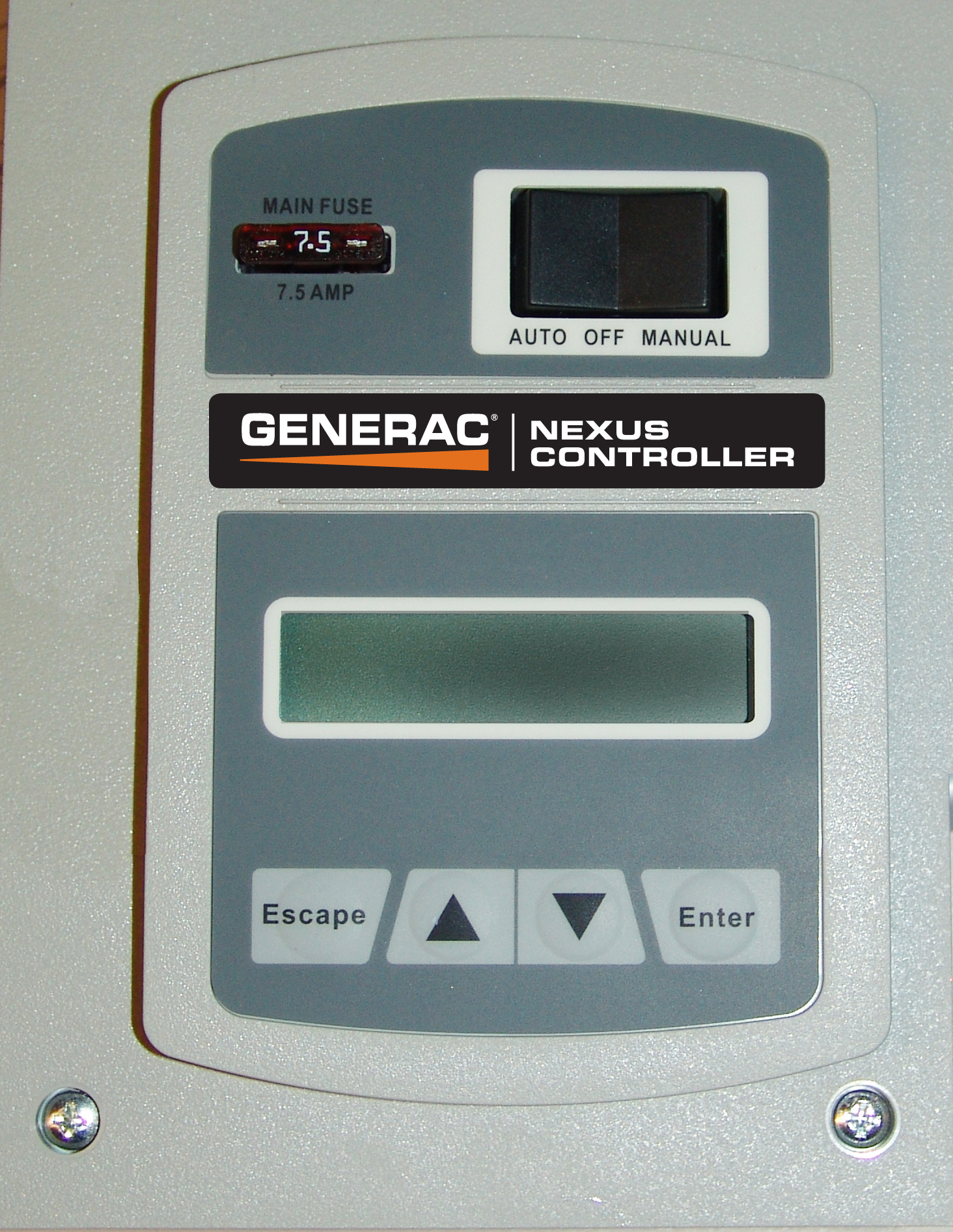
This project will monitor a backup generator that utilizes the Generac Evolution or Nexus Controllers over a WiFi or wired connection. Generac, Eaton, Honeywell and Siemens Home Backup Generators use these Generac controllers. Honeywell and Eaton call the controllers Sync 1.0 (Nexus) and Sync 2.0 (Evolution) in their documentation however all of these companies sell generators that use the controllers supported by this project. The project is written mostly in python and has been tested with a Raspberry Pi 3 (Pi Zero and Pi 2 has also been validated). Ideally you would need to create a physical enclosure for your raspberry pi and possibly make a cable to connect the raspberry pi to the Evolution or Nexus controller. If you are comfortable doing these things and you have a backup generator that has an Generac Evolution or Nexus controller then this project may be of interest to you.
The software supports the following features:
- Monitoring of the generator to to detect and report the following:
- Maintenance, Start / Stop and Alarm Logs (No Maintenance log exist on Nexus)
- Display Generator Serial Number
- Generator warnings and faults
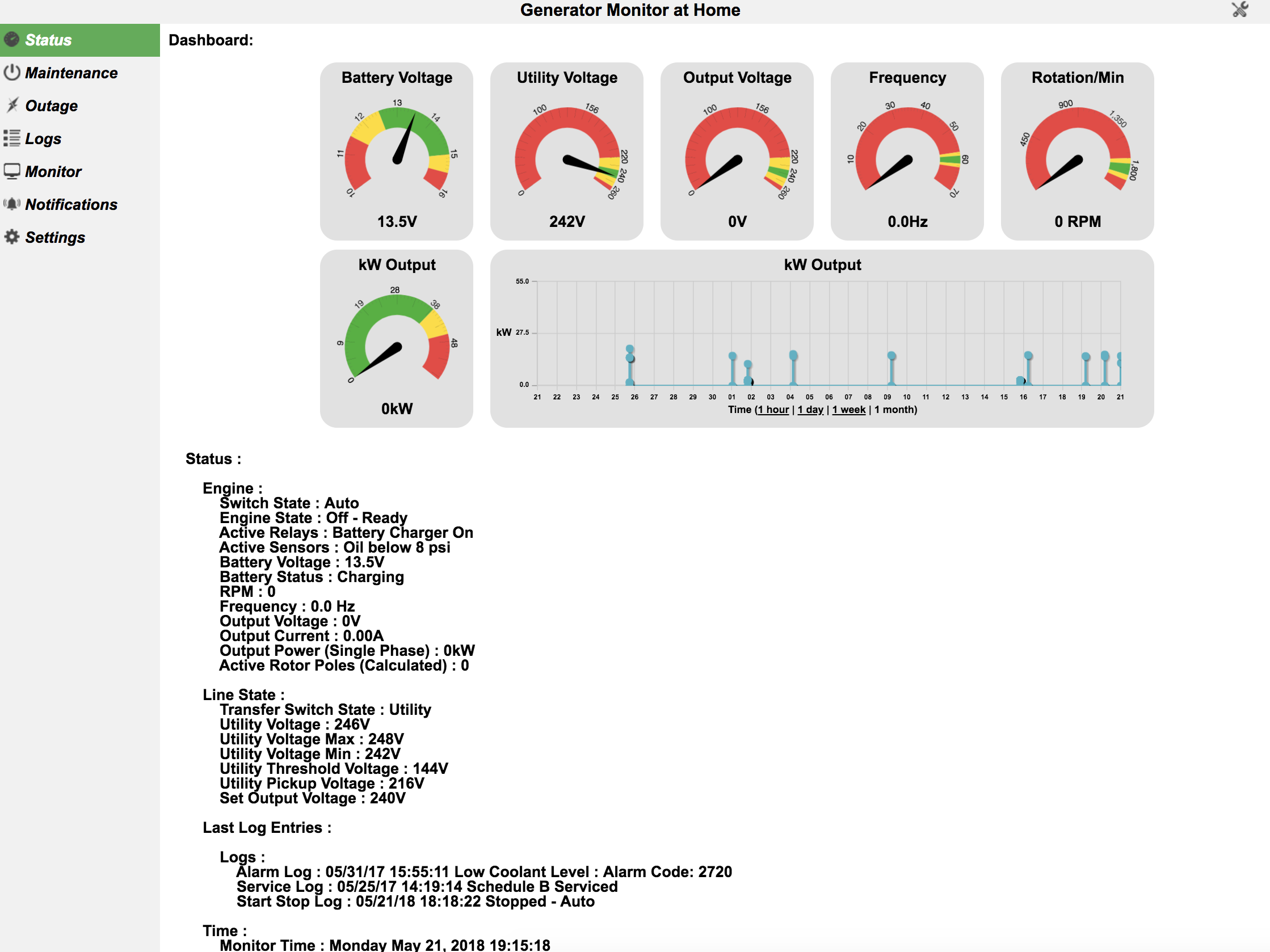
- Generator Status:
- Engine State
- Generator Switch State (Auto, On, Off)
- Generator Engine State (Stopped, Starting, Exercising, Running Manual, Running Utility Loss, Stopped due to Alarm, Cooling Down)
- Battery Voltage and Charging Status
- Relay Output State: (Starter, Fuel Relay, Battery Charger, others for liquid cooled models)
- Engine RPM, Hz and Voltage Output
- Generator Controller Time
- Line State
- Utility Voltage Level
- Transfer Switch State (Evolution liquid cooled models only)
- Outage Information
- Time since last outage
- Current Utility Voltage
- Min and Max Utility Voltage since program started
- Maintenance Information
- Weekly Exercise time, day (biweekly and monthly if supported by your generator)
- Hours till next scheduled service
- Total Run Hours
- Firmware and Hardware versions
- Various statics from the generator monitor including time since program launched, MODBUS / serial communications health and program health.
- Engine State
- Email notification of :
- Engine state change
- Switch state change
- Critical or Warning messages from the generator
- Web based application for viewing status of the generator
- SMS notifications of Generator state (via Twilio SMS API)
- Push notifications (via pushover.net)
- syslog logging of generator events
- Command Line application (all the functionality of email).
- Ability to set exercise time
- Ability to set generator time
- Ability to start, stop, exercise and start / active the transfer switch (i.e. power your house off the generator) remotely.
This project is free to use under the posted license agreement. It was written and is supported by one person with testing and some documentation supported by users of the software. I originally created this project for my personal use however I decided to make the project available to anyone interested, however I do accept tips via paypal:

This software was written by one person with full time access to one generator. The primary model used for testing and development is a liquid cooled model with an evolution controller. The software was written with every intention of working on liquid and air-cooled models with the Evolution or Nexus controller however the author has not tested all scenarios. Testing has been performed with both Evolution and Nexus Controllers (air cooled and liquid cooled) with help of the community, however not all firmware versions and models have been tested.
In an effort to expand compatibility and functionality, from time to time I may use the issue tracker of this project to request input from people using the software. This input will will allow greater compatibility and new features to be added.
Nexus Controllers are currently supported however the functionality is reduced due to the Nexus Controller supporting fewer features. On Nexus Controllers the ability to detect battery charging, transfer switch relay state and set the quiet mode is not functional. All other functionality support by the genmon.py and the Nexus controller should work as expected.
If the legacy method of setting the exercise time is used (it is used on all Nexus controllers) then you can only set a future time on the current day of the week. You can set the exercise time to any day and time, except earlier in the day on the current day of the week.
While a large amount of functionality is included in this software, some items may be missing. For example, the Evolution Controller has the concept of alarm log entries and alarm codes. Alarm log entries are the collection of the time, date and a description of a give alarm along with an alarm code. Alarm codes are a 4 digit number that corresponds to a specific alarm condition. The alarm codes and the alarm log may not display every alarm log entry properly in the user interface. I have attempted to decode these values and according to the documentation I have decoded many, if not most, of them. If you run into a situation where the one of the logs entries or values returned reports and unknown value feel free to let me know (via opening a project issue). Generally this can be easily resolved by sending the decoded log values supplied in the email or web interface and a picture of the corresponding log entry (match the time and date and alarm code) from the Controller display. This really comes down to a list of numbers that correspond to displayed strings in the Evolution Controller firmware. My generator only has a finite set of alarm log entries so not every string displayed may be decoded my genmon.py. The alarm conditions and alarm codes are in the file ALARMS.txt. The list of alarm codes was taken from the Generac documentation so this list is likely close to complete however the short description of the alarm contained in the alarm log may need input from others to complete. Input from others on unknown logs and alarms can be submitted here and here
For Evolution Controllers, the software will show the state the some active relays (Starter, Fuel Relay etc). These relays differ slightly from air cooled to liquid cooled models. The software shows the state of the relay in the controller, not the actual state of what the relay is driving. For example, if the active relay states that the Transfer Switch (Evo Liquid Cooled models) is active, this means that the controller is attempting to activate the transfer switch. If something is wrong with your switch or the connection is bad between the relay and the switch, your transfer switch may not truly be activated (i.e. there is no feedback mechanism back to the controller). If you generator is working properly then you can expect the relays to match what they are driving.
To summarize, if you see any unknown or things are not working as expected, please open an issue on the project.
If you have a large generator, the placement of your Raspberry Pi could be important due to EMI. Larger generators can produce more EMI when starting. For example a 48kw diesel generator may generate enough EMI to cause CRC errors when the generator starts if the Raspberry Pi enclosure is close to the engine. If you see CRC errors, check the validity of your cable. The errors may be caused by vibration of loose molex connectors in your cable. Also, if the Raspberry Pi enclosure is moved away from the engine and closer to the controller, this will likely reduce EMI if that is causing any CRC errors. EMI may not be an issue with smaller liquid cooled generators. There are several ways to resolve EMI issues however the best solution is dependent on your particular site needs (generator, how much space you need for your Pi, how much space you have available, etc). The project wiki has information regarding a typical enclosure for the Raspberry Pi, however the example enclosure is not RF shielded.
This application was written to be agnostic of the underlying network media (i.e. WiFi, Ethernet, etc). Testing and development was performed with WiFi. WiFi access points were connected to an uninterruptible power supply (UPS) so connectivity is not lost power is transferred from the utility to the generator.
Since there are several version of the raspberry Pi out and also several options regarding the operating system, I will leave this section somewhat minimal. I used a Raspberry Pi 3 with Raspbian Lite. There are many resources on the web for setting up a Raspberry Pi so I will only include links for setting up the serial port. The Linux device name of the serial port changed or at least the symbolic link changed starting with the Raspberry Pi 3 from /dev/ttyAMA0 to /dev/serial0 so if you are using the on board serial port you will want to validate the device name and make sure genmon.conf reflects the serial device name of your Raspberry Pi and Linux distribution. The following two links are helpful in setting up the serial port on the Raspberry Pi:
General Setup of the serial port for a Raspberry Pi
An updated serial port setup instructions based on the Raspberry Pi 3
One important step is to validate your serial port is working properly. You can validate the serial port is working properly by using the program serialtest.py in this repository. To validate your serial port connect the RS-232 transmit to RS-232 receive and follow the instructions in the software section on serialtest.py. Also, you can validate your cable by connecting your cable to your serial port and connecting transmit to receive at the far end of the cable so you will be looping back through your cable, then repeat the serialtest.py test.