


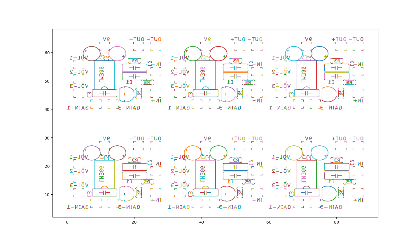
using CAM files and a bit of manual prep we can generate a gcode file to run a laser to etch the component side of the board.
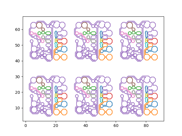
You can now use this to nest g-code (non-rotationally) to fill out a PCB
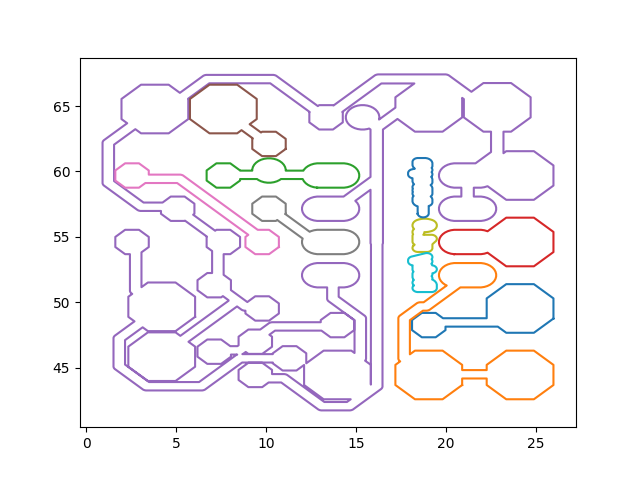
input g-code with outlines at a random spot X,Y
we then move the g-code to 0,0

then we nest it as many times as possible
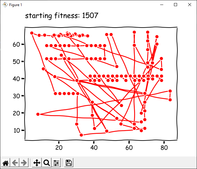
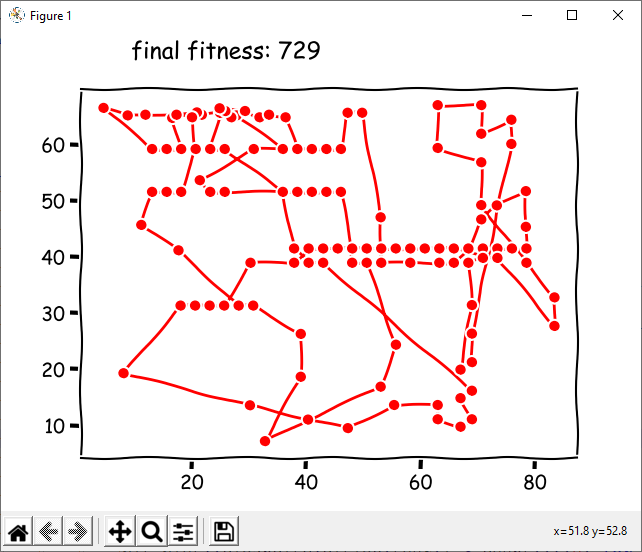
take gcode and do a poor job trying to optimize it
The gcode that we start with looks something like this
After running this crappy code it looks something like this
in eagle
run ULP 'pcb-gcode-setup' to get bottom etch and drill files
file > 'generate CAM data' (cam data is used in flamcam in next step)
in flatcam
'open_gerber <top-silkscreen-file.cam> -follow 1 -outname GTO_follow'
'follow GTO_follow -outname silk_geo'
'cncjob silk_geo'
'write_gcode silk_geo_cnc silk.gcode'
in notepad
edit silk.gcode from flatcam
remove headers/footers
find and replace (include trailing/leading spaces as indicated):

	'Y' -> ' Y'
	'\n' -> '\nN0 '
	'G01 Z-0.0020' -> 'M03'
	'G00 Z0.1000' -> 'M05'
in gcodestuff
run and select the 3 files we created above