8580 AC Voltage divider
The two big capacitors are part of a trick circuitry which changes the gate voltage of the frequency control DACs according to the temperature of the DACs, to reduce the effects of temperature to the filter curve.
There is a FET working as a temperature sensor close to the DACs, but we are getting there later.

We have an asynchronous 3 bit binary counter, LSB is running at the speed of PHI2. Every counter bit drives a R\S flipflop for making the inverted and non_inverted output of the bit non_overlapping. From the logic design point of view, those three bits in the counter are pretty similar on the silicon, the transistors in the R\S flipflop output of the MSB are just a bit bigger and +9V powered.

The two big capacitors and the +9V powered switches "between" them:
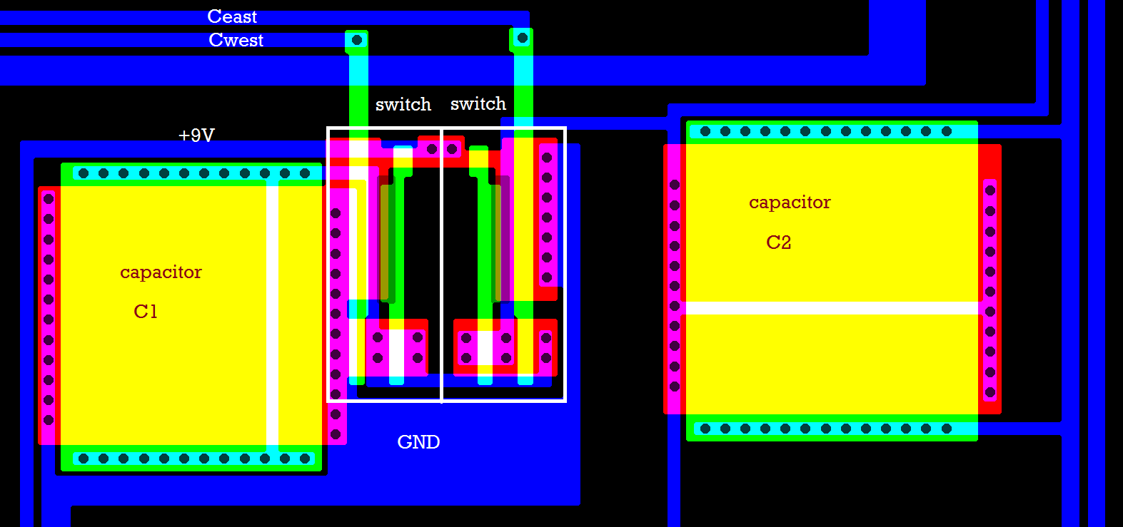
It's an ingenious idea to use the AC resistance of two capacitors as a voltage divider. The AC resistance of the two capacitors depends on the PHI2 clock frequency, while the resistance of the temperature sensor FET does not. This implicates, that when taking a PAL C64 and modiying it into a NTSC C64, or vice versa, this might shift the filter curve by 4% or such.