-
Notifications
You must be signed in to change notification settings - Fork 0
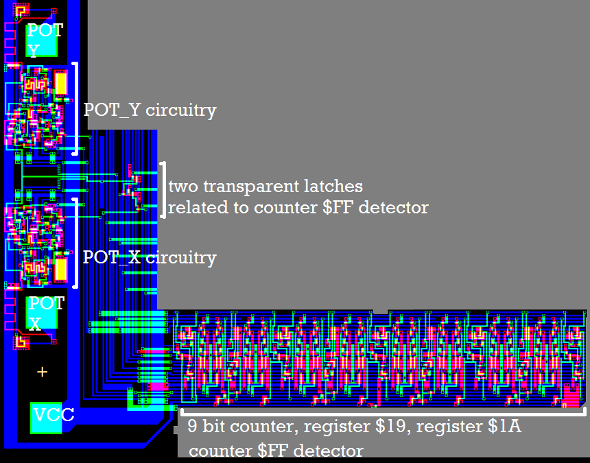
Paddles Overview
Now about the paddle related stuff:

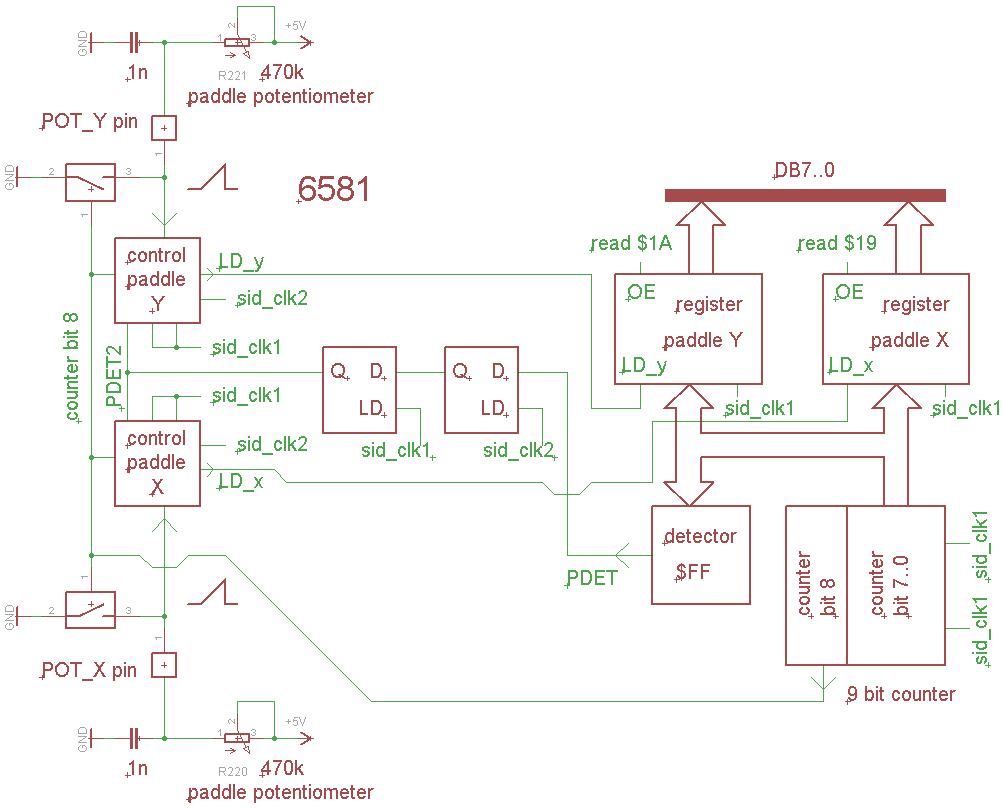
Block diagram:

We have a 9 bit counter running at PHI2 speed.
Bit 7..0 from the counter are fed into two 8 bit latches, POT_X and POT_Y.
At the POT_X pin, we have an external capacitor, which is charged through the paddle potentiometer resistance to +5V.
When the voltage at the POT_X pin has reached a certain level, the value from the counter is loaded into the POT_X register.
Also, when the coutner has reached $FF (maybe because the paddle potentiometer is missing), there is some circuitry that forces loading the counter value into POT_X.
It's a 9 bit counter, while the counter MSB ( bit 8 ) is 1, the external capacitor is discharged through a FET in the SID which is close to the POT_X pin.
Same thing for POT_Y.
So one "conversion" from paddle potentiometer position to POT_X,POT_Y value happens within every 512 PHI2 clock cycles.
Note, that PHI2 clock frequency is different for a PAL and a NTSC C64.
If the capacitors at the POT_X, POT_Y pins in both C64s would have exactly the same value (usualy, they haven't), and if the +5V supply voltages in both C64s would be exactly the same (usually, it isn't), reading out one and the same paddle position on both C64s probably might give you a value that differs by 4% or such.
Clock
Reset
Address Decoders
Data Bus
Registers
Oscillator
Pulse Waveform
Triangle Waveform
Noise Generator
Wave Selector
Envelope Overview
Envelope Counter
Sustain Comparator
ADSR registers
Counter Logic
Exponential Divider
LFSR15 counter
LFSR5 counter
Analog stage overview
6581 DACs
6581 Opamps
6581 Filter overview
6581 Audio output
8580 DACs
8580 Virtual ground
8580 AC Voltage divider
8580 Opamps
8580 Filter overview